
























APOYO TÉCNICO


Publicado 2026-07-18
01kpotencia servoGuía de cableado: cuántos cables y cómo conectarlos correctamente
Respuesta rápida
Más estándarkpotencia servoLos motores utilizan una configuración de tres cables: alimentación (VCC), tierra (GND) y señal. Conectarlos correctamente requiere niveles de voltaje coincidentes para evitar quemar (quemar) componentes y garantizar que la polaridad de la señal se alinee con su controlador. El cableado incorrecto provoca fallas inmediatas del hardware, movimientos erráticos o riesgos de seguridad. Verifique siempre la hoja de datos de su modelo específico antes de realizar la conexión, ya que las variantes industriales pueden incluir retroalimentación o líneas de freno adicionales.
La importancia crítica de lo correctoservoAlambrado
En la automatización industrial, un solo error de cableado puede detener las líneas de producción, dañar actuadores costosos y comprometer la seguridad del sistema. Muchos ingenieros y gerentes de adquisiciones subestiman la complejidad de la servointegración, asumiendo que todos los motores se conectan de manera idéntica. Esta suposición es peligrosa. Los servosistemas funcionan según protocolos eléctricos y de comunicación precisos. La mala interpretación de las funciones de los cables, como intercambiar energía y tierra o confundir tipos de señales, produce fallas catastróficas. Comprender la interfaz física no es sólo un detalle técnico;kpotenciaservoproductos, el cumplimiento de estrictos estándares de cableado garantiza un rendimiento óptimo, longevidad y un tiempo de inactividad mínimo. El costo de la prevención es significativamente menor que el costo de reemplazo y reparación.
Comprender la configuración estándar de tres cables
La gran mayoría de los servos digitales modernos, incluidos los dekpower servo , utilize a standardized three-wire connection scheme. This simplicity belies the complexity of the signals transmitted through each conductor.
1. Power Supply (VCC/Positive): This wire delivers the main operating voltage to the motor. It is critical to match this voltage precisely to the servo's rated input. Overvoltage causes thermal runaway and insulation breakdown; undervoltage leads to torque loss and stalling.
2. Ground (GND/Negative): This completes the electrical circuit and provides a common reference point for the signal. A poor ground connection introduces noise, leading to unstable control and erratic movement.
3. Control Signal (Signal/PWM): This wire carries the pulse-width modulation (PWM) commands from the controller. It dictates the position, speed, and torque of the motor.
While three wires are standard, some advanced models may include additional wires for brake engagement, encoder feedback, or shield grounding. Always consult the specific product manual for selección de servomotor to confirm the exact pinout.
Detailed Pinout and Connection Logic
To ensure seamless integration, you must understand the function and color coding of each wire. Although color codes can vary by manufacturer, the functional logic remains consistent across high-quality brands like kpower servo .
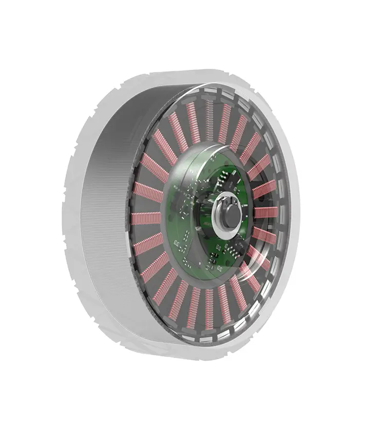
Red Wire (typically): Represents the positive power supply (+VCC). Connect this to the positive terminal of your power source. Ensure the voltage matches the servo's rating (eg, 24VDC, 48VDC).
Black or Brown Wire (typically): Represents the ground (-GND). Connect this to the negative terminal of the power source and the controller's ground.
Yellow, Orange, or White Wire (typically): Represents the control signal. Connect this to the PWM output channel of your motion controller or PLC.
If your servo includes a brake, there will be a fourth wire, often blue or green, which activates the mechanical brake when de-energized. For servosoluciones personalizadas , additional wires may handle analog feedback or digital communication protocols like EtherCAT or CANopen.
Common Wiring Mistakes and Their Consequences
Even experienced technicians make errors when dealing with high-power electronics. Recognizing these pitfalls is essential for maintaining system integrity.
These errors highlight why requisitos de par and electrical specifications must be reviewed thoroughly. A small oversight in wiring can lead to significant financial loss and operational delays.
Verifying Compatibility and Standards
Before integrating any servo into your system, verification is key. Different industries have varying standards for connector types, voltage levels, and signal protocols. kpower servo products are designed to meet international standards, but compatibility depends on your specific setup.
Check the following parameters:
Rango de voltaje: Does your power supply fall within the servo's acceptable range?
Current Capacity: Can your power supply deliver the peak current required during acceleration?
Signal Type: Is your controller outputting the correct PWM frequency and voltage level for the servo's input?

Connector Type: Do the physical connectors match, or do you need adapters?
For complex applications, consider aplicaciones de control de movimiento that require high precision. In such cases, using shielded cables and proper grounding techniques can mitigate electromagnetic interference (EMI), ensuring stable performance.
Practical Checklist for Installation
To streamline your installation process, follow this checklist:
1. Disconnect Power: Always de-energize the system before making any connections.
2. Identify Wires: Confirm the function of each wire using the servo's datasheet.
3. Match Voltages: Ensure the power supply voltage matches the servo's requirement.
4. Secure Connections: Tighten all terminals to prevent vibration-induced loosening.
5. Test Signal: Before full power, test the signal line with a multimeter or oscilloscope if possible.
6. Gradual Power-Up: Apply power slowly and monitor for abnormal behavior.
This systematic approach reduces risk and ensures a smooth commissioning phase. For buyers comparing similar options, paying attention to these details separates professional installations from amateur attempts.
Common Questions About Servo Wiring
Q: What happens if I connect the signal wire to power?
A: This will likely destroy the servo's control circuitry immediately. Always verify wire functions before connecting.
Q: Can I use a 5V signal for a 24V servo?
A: Not directly. You may need a level shifter or a controller that outputs compatible voltage levels to avoid damaging the input.
Q: Why does my servo vibrate after installation?
A: This is often caused by loose ground connections, incorrect tuning, or electromagnetic interference from unshielded cables.
Q: Do I need a separate power supply for the servo?
A: Yes, it is recommended. Using a dedicated supply prevents noise from affecting other sensitive electronics and ensures stable voltage delivery.
Q: How do I identify the brake wire?
A: Consult the datasheet. It is usually a distinct color and connects to a separate control circuit that engages the brake when powered off.
Q: Can I daisy-chain multiple servos on one signal line?
A: Generally, no. Each servo typically requires a dedicated signal line from the controller to ensure precise individual control.
Tomar una mejor decisión a largo plazo
Correct wiring is not merely a technical step; it is a strategic investment in your automation infrastructure. By understanding the nuances of selección de servomotor and adhering to best practices, you minimize downtime and extend equipment life. Whether you are upgrading existing machinery or designing a new system, prioritizing electrical integrity yields significant returns.
For tailored advice on your specific application, our engineering team is ready to assist. Contact us to request a quote for your servo needs or schedule a consultation to review your wiring diagrams. Ensure your project succeeds with reliable, high-performance kpower servosoluciones.
Update Time:2026-07-18

Comuníquese con el especialista en productos de Kpower para recomendarle un motor o caja de cambios adecuado para su producto.


