
























الدعم الفني


تم النشر 2026-07-08
عنوان تحسين محركات البحث: كيف يمكن لـمضاعفاتالعمل الحركي؟ دليل عملي لأساليب التحكم
الوصف التعريفي: فهم مبدأ العمل وطرق التحكممضاعفاتالمحركات. تعرف على كيفية تأثير PWM وحلقات التغذية المرتدة وعزم الدوران على التحكم في الحركة في التطبيقات الصناعية.
إجابة سريعة
أمضاعفاتمحركيعمل على نظام تحكم مغلق الحلقة يقارن موضع الهدف أو عزم الدوران بالتغذية المرتدة الفعلية من جهاز التشفير أو المحلل. يقوم بضبط الإخراج بشكل مستمر لتقليل الخطأ. طريقة التحكم الأساسية هي تعديل عرض النبض (PWM)، حيث يحدد عرض النبضة الكهربائية الموقع الزاوي للمحرك أو سرعته. هذا المزيج من ردود الفعل السريعة والتحكم الدقيق في الإشارة يجعل المحركات المؤازرة مثالية للتطبيقات التي تتطلب حركة دقيقة، مثل التصنيع باستخدام الحاسب الآلي، والروبوتات، وتغليف الخطوط. بدون تغليف. عند ضبط إشارات التحكم أو مطابقتها بشكل مناسب لمتطلبات التحميل، يتدهور الأداء بسرعة.
مقدمة
توقف خط الإنتاج بشكل متكرر. تتجاوز الذراع الآلية موضعها المستهدف بمقدار ملليمترات في كل دورة. ترفض آلة التعبئة والتغليف المنتجات لأن توقيت كل حركة يتم إيقافه بالمللي ثانية.
تشترك هذه الأعراض في جذر مشترك: عدم كفاية التحكم في الحركة. غالبًا ما يفترض المهندسون ومديرو المشتريات أن أي محرك مزود بجهاز تشفير مؤهل ليكون بمثابة جهاز مؤازر. في الواقع، يكمن الفرق بين تحديد المواقع الموثوق به والانجراف المستمر في كيفية تفسير المحرك لإشارات التحكم وتصحيح سلوكه.
تكلفة سوء فهم التحكم المؤازر مباشرة: المواد المهدرة، وأوقات الدورات البطيئة، وزيادة الصيانة، وارتفاع معدلات الرفض. بالنسبة للمشترين الذين يقومون بتقييم المكونات المتحركة، فإن السؤال ليس ببساطة "هل يتحرك"، ولكن "كيف يحافظ على موضعه تحت الحمل المتغير".
إن فهم مبدأ العمل وطرق التحكم ليس بالأمر الأكاديمي. إنه الأساس لتحديد النظام الصحيح وتقليل مخاطر التكامل وتحقيق مخرجات متسقة.
جدول المحتويات
1. المبدأ الأساسي: التحكم في ردود الفعل ذات الحلقة المغلقة
2. كيف يتحكم تعديل عرض النبض (PWM) في الموضع والسرعة
3. المكونات الرئيسية التي تمكن الحركة الدقيقة
4. طرق التحكم: أوضاع الوضع والسرعة وعزم الدوران
5. الأخطاء الشائعة في اختيار التحكم المؤازر
6. الأسئلة التي يطرحها المشترون غالبًا حول التحكم المؤازر
7. اختيار أسلوب التحكم الصحيح لتطبيقك
المبدأ الأساسي: التحكم في ردود الفعل ذات الحلقة المغلقة
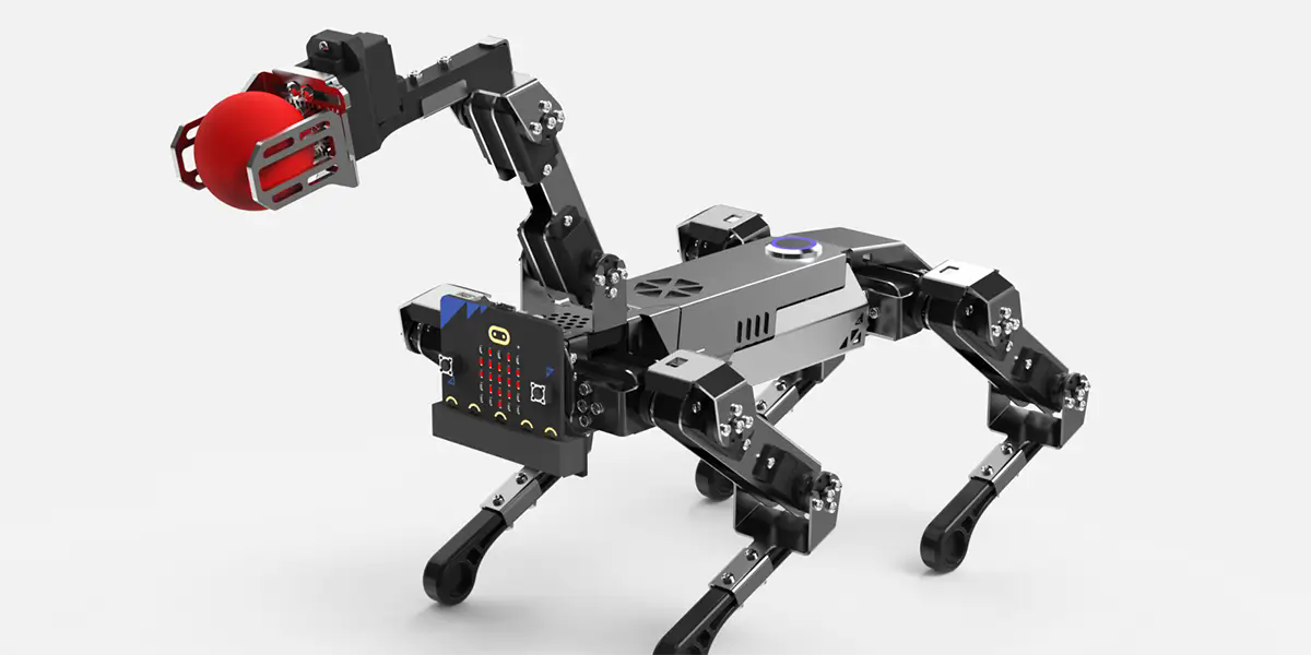
الفرق الجوهري بين أمحرك سيرفووالمحرك القياسي هو حلقة التغذية المرتدة. يعمل المحرك التعريفي القياسي بحلقة مفتوحة: حيث تقوم بتطبيق الطاقة، ويدور دون الإبلاغ عن موضعه أو سرعته الفعلية.
محرك سيرفو يفعل العكس. فهو يقارن باستمرار القيمة المطلوبة - الموضع أو السرعة أو عزم الدوران - مقابل القيمة الفعلية التي يتم قياسها بواسطة جهاز التغذية الراجعة. في حالة وجود انحراف، تقوم وحدة التحكم بضبط خرج الطاقة لتصحيحه. ويحدث هذا التصحيح مئات أو آلاف المرات في الثانية الواحدة.
إن بنية الحلقة المغلقة هذه هي السبب وراء قدرة أنظمة المؤازرة على الاحتفاظ بموضعها تحت أحمال مختلفة. عندما تلتقط الذراع الآلية جزءًا أثقل، يزداد الطلب على عزم الدوران. تكتشف وحدة التحكم المؤازرة انخفاض السرعة وزيادة التيار وتعيد الذراع إلى الموضع المطلوب قبل أن يصبح الخطأ مرئيًا.
بدون حلقة التغذية الراجعة هذه، حتى المحرك الأقوى لا يمكنه ضمان تحديد موضع متكرر. بالنسبة للتطبيقات التي يتم فيها قياس التسامح بالميكرونات أو المللي ثانية، فإن التحكم في الحلقة المغلقة ليس اختياريًا.
كيف يتحكم تعديل عرض النبض (PWM) في الموضع والسرعة
الطريقة الأكثر شيوعًا للتحكم في المؤازرة هي تعديل عرض النبض (PWM). إشارة PWM عبارة عن موجة مربعة حيث تحدد مدة نبضة "التشغيل" - المُقاسة بالمللي ثانية - استجابة المحرك.
بالنسبة لماكينات التحكم القياسية في الموضع، فإن نبضة تبلغ 1.0 مللي ثانية تتطلب عادةً دورانًا كاملاً في اتجاه واحد، ونبضة تبلغ 1.5 مللي ثانية في موضع مركز الأوامر (محايد)، ونبضة تبلغ 2.0 مللي ثانية تأمر بالدوران الكامل في الاتجاه المعاكس. تقرأ وحدة التحكم عرض النبضة، وتقارنها بموضع التغذية المرتدة الحالي، وتقوم بتشغيل المحرك للمطابقة.
في محركات المؤازرة الرقمية الأكثر تقدمًا، يعمل PWM بترددات أعلى. التردد العالي يقلل من الضوضاء المسموعة ويحسن وقت الاستجابة. يختلف نطاق عرض النبض والنقطة المحايدة حسب الشركة المصنعة ويجب التحقق منه وفقًا لمواصفات محرك الأقراص.
يتبع التحكم في السرعة عبر PWM منطقًا مشابهًا ولكنه يفسر عرض النبضة على أنها سرعة مستهدفة بدلاً من موضع ثابت. في الماكينات ذات الدوران المستمر، يحدد عرض النبضة أعلى أو أسفل النقطة المحايدة الاتجاه والسرعة المتناسبة.
للمشترين اختيار أservo motor system , confirming the PWM compatibility between the controller and the drive is a critical step. Mismatched signal ranges cause erratic movement or complete loss of control.
Key Components That Enable Precise Movement
A servo system includes four essential elements: the motor, the feedback device, the drive, and the controller.
المحرك: Typically a brushless DC (BLDC) or AC synchronous motor designed for rapid acceleration and deceleration.
Feedback device: An encoder or resolver that reports actual position, speed, or torque. Resolvers are more robust in high-vibration environments, while encoders offer higher resolution.
Drive (amplifier): Converts low-power control signals into high-power current for the motor. It also interprets feedback and adjusts output.
المراقب المالي: The brain of the system. It generates the command signal based on the application program and receives feedback from the drive.
The quality of each component directly affects system performance. A high-resolution encoder improves position accuracy but increases system cost. A resolver may be more reliable in dirty environments but offers lower resolution.
Buyers should evaluate the feedback type based on the operating environment, required accuracy, and maintenance schedule. In many industrial applications, the feedback device is the first component to fail when exposed to excessive heat or contamination.
Control Methods: Position, Speed, and Torque Modes
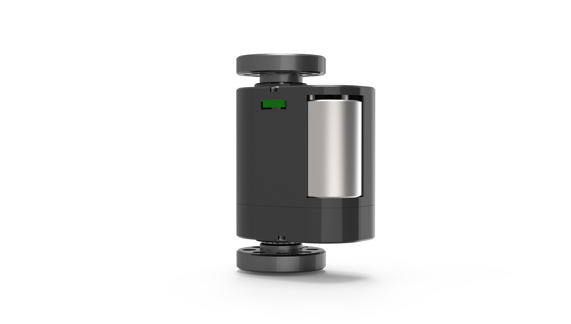
Modern servo drives support multiple control modes. Selecting the correct mode depends on the application requirement.
Position mode: The most common. The controller sends a target position, and the servo moves to that position with specified acceleration and deceleration. Used in pick-and-place, CNC positioning, and indexing.
Speed mode: The controller sends a target velocity. The servo maintains that speed regardless of load variations within its torque limit. Used in conveyors, spindles, and winding machines.
Torque mode: The controller sends a target current value. The servo applies a constant torque regardless of speed. Used in tension control, pressing, and clamping applications.
Many advanced drives allow switching between modes during operation. For example, a machine may use torque mode during a pressing phase, then switch to position mode for the return stroke.
Choosing the wrong mode increases cycle time and reduces process consistency. A buyer specifying a servo for a motion control application should define the primary control requirement before selecting the drive.
Common Errors in Servo Control Selection
Several recurring mistakes increase project cost and delay commissioning.
First, underestimating required torque. Buyers often calculate average torque but ignore peak torque during acceleration. A servo motor that meets average torque but cannot handle peak demand will stall or trigger an overcurrent fault.
Second, ignoring inertia ratio. The load-to-motor inertia ratio should typically stay below 10:1. Higher ratios make tuning difficult, cause overshoot, and reduce positioning stability.
Third, assuming all PWM signals are compatible. Servo drives from different manufacturers may use different pulse widths, logic levels, or polarity. Always confirm the control signal specification with the مورد محرك سيرفو .
Fourth, neglecting cable quality and length. Long or unshielded cables introduce noise into the feedback signal. Noise causes jitter, drift, or complete loss of position.
Fifth, skipping system tuning. Even a correctly sized servo system performs poorly without proper gain tuning. Tuning adjusts how aggressively the controller responds to errors. Over-tuned systems oscillate. Under-tuned systems are slow and inaccurate.
Questions Buyers Often Ask About Servo Control
Q: What is the difference between a servo motor and a stepper motor?
A servo motor uses closed-loop feedback and can maintain position under varying loads. A stepper motor moves in discrete steps and often operates open-loop. Servos are better for high-speed, high-torque, or variable-load applications. Steppers are simpler and lower-cost for low-speed, constant-load tasks.
Q: How do I choose between an analog and a digital servo drive?
Analog drives accept ±10 V signals and are simpler but less precise. Digital drives accept PWM, fieldbus, or Ethernet commands and offer advanced tuning, diagnostics, and multi-mode control. For new industrial installations, digital drives are the standard choice.
Q: Can I use a servo motor without a drive?
No. A servo motor requires a drive to convert low-power control signals into the high-current waveform needed for operation. Connecting a servo motor directly to a power source will not produce controlled motion and may damage the motor.
Q: What does “servo tuning” mean?
Tuning is the process of adjusting PID (proportional-integral-derivative) gains in the drive or controller to match the mechanical system. Proper tuning minimizes overshoot, settling time, and steady-state error. Incorrect tuning causes oscillation, noise, or slow response.
Q: How does cable length affect servo performance?
Long feedback cables increase resistance and susceptibility to electrical noise. For encoder signals, cable lengths above 10–15 meters typically require differential signaling or a signal repeater. Power cables should be shielded and separated from control cables.
Q: What is the typical lifespan of a servo motor brush?
Brushless servo motors have no brushes. Their lifespan depends on bearing quality, operating temperature, and load. In typical industrial environments, a brushless servo motor operates 20,000 to 40,000 hours before bearing replacement is needed.
Q: Can a servo motor hold position without power?
No. Most servo motors do not have a mechanical brake. When power is removed, the motor free-spins unless a separate holding brake is integrated. For vertical or gravity-loaded axes, a brake is required for safety.
Q: What is the difference between incremental and absolute encoders?
An incremental encoder reports relative position changes from a reference point. An absolute encoder reports exact position at all times, even after power loss. Absolute encoders eliminate the need for a homing routine but cost more and require battery backup in some designs.
Choosing the Right Control Approach for Your Application
Selecting a servo control method begins with defining the motion profile: Is the task position-critical, speed-critical, or torque-critical? The answer determines whether you need a position, speed, or torque mode system.
Next, evaluate the operating environment. High temperature, vibration, or electrical noise influence feedback type, cable specification, and drive enclosure rating. An industrial محرك سيرفو installed near a welding line requires different protection than one in a cleanroom.
Then, consider the controller compatibility. Not all controllers support all fieldbus protocols. If your existing PLC uses EtherCAT, the servo drive must support EtherCAT. Protocol mismatch is a common integration obstacle.
Finally, work with a supplier who provides detailed specifications, application support, and tuning guidance. A servo system is not a plug-and-play component. The difference between a system that barely works and one that delivers consistent throughput often comes down to proper sizing, control method selection, and commissioning support.
فيkpowerمضاعفات , we help buyers evaluate their motion requirements, match control methods to application needs, and avoid common integration errors. If you are currently comparing servo options or need assistance selecting the right control approach, contact our engineering team with your application details.
وقت التحديث: 2026-07-08


