



























الدعم الفني


تم النشر 2026-07-12
إجابة سريعة
أبوممضاعفاتلوحة القيادةيترجم إشارات التحكم إلى حركة محرك دقيقة، ولكن لا توفر جميع اللوحات نفس الدقة أو إدارة الحرارة أو التزامن متعدد المحاور. غالبًا ما يؤدي اختيار اللوحة الخاطئة إلى اهتزاز، أو ارتفاع درجة الحرارة، أو فشل تسلسل الحركة - خاصة في الألعاب المتعددة.مضاعفاتتطبيقات مثل الروبوتات أو CNC أو الأتمتة الصناعية. يجب أن تتوافق اللوحة اليمنى مع نطاق الجهد الكهربي ودقة الإشارة ومعدل التحديث والتصميم الحراري. قبل الشراء، تحقق من تردد PWM الخاص باللوحة، والتصنيف الحالي لكل قناة، وميزات الحماية لتجنب الأعطال الميدانية التي تزيد من إجمالي تكلفة الملكية.
01مقدمة
في كل عام، تخسر فرق الإنتاج آلاف الدولارات ليس بسبب عملهممضاعفاتs معيبة، ولكن لأنلوحة قيادة مؤازرة PWMلقد اختاروا عدم القدرة على التعامل مع حمل العالم الحقيقي. حركات ذراع متوترة على خط الانتقاء والمكان. ارتفاع درجة الحرارة أثناء فترة التشغيل الممتدة. الماكينات التي تفقد موضعها في منتصف الدورة. نادرًا ما تشير هذه الأعراض إلى المحرك نفسه، بل تشير إلى لوحة القيادة.
عندما تقوم بإدارة نظام متعدد المحاور، تصبح اللوحة هي الجهاز العصبي المركزي. إذا لم يتمكن من تقديم إشارات PWM نظيفة ومتسقة تحت الحمل الكامل، فسوف يتدهور تسلسل الحركة بالكامل. والأسوأ من ذلك أن الإجهاد الحراري المتكرر يؤدي إلى تقصير عمر المكونات، مما يجبر على إجراء عمليات استبدال مبكرة مما يؤدي إلى تآكل ميزانيات الصيانة. المشكلة ليست في نقص الخيارات. تكمن المشكلة في فصل اللوحات المصممة للنماذج الأولية للهوايات عن اللوحات المصممة للخدمة الصناعية المستمرة.
02جدول المحتويات
1. ما الذي تفعله لوحة تشغيل PWM Servo فعليًا
2. المواصفات الرئيسية التي تحدد الأداء في العالم الحقيقي
3. كيف يؤثر تصميم اللوحة على الحرارة والارتعاش وفقدان الإشارة
4. التنسيق متعدد المحاور: لماذا لا يكفي عدد القنوات
5. الأخطاء الشائعة عند اختيار لوحة القيادة
6. جدول مقارنة المواصفات
7. الأسئلة التي يطرحها المشترون غالبًا حول لوحات التشغيل المؤازرة PWM
8. اختيار اللوحة المناسبة لتطبيقك
03ما الذي تفعله لوحة تشغيل PWM Servo فعليًا
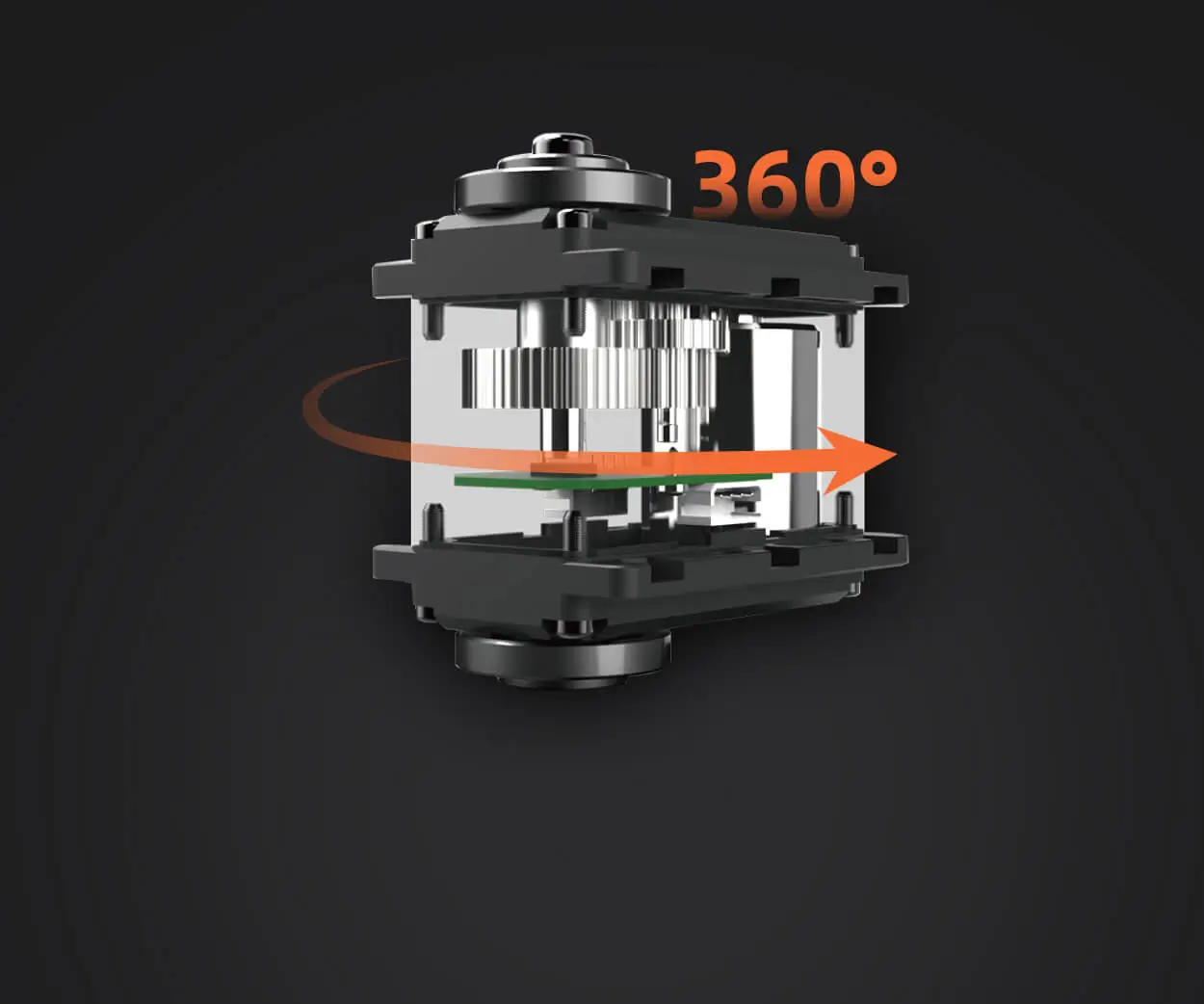
تستقبل لوحة التشغيل المؤازرة PWM إشارة معدلة بعرض النبضة - عادةً ما بين 1 مللي ثانية و 2 مللي ثانية عند 50 هرتز - وتحولها إلى موضع زاوي مناسب على المؤازرة. بالنسبة إلى مؤازرة واحدة، تعمل أي لوحة أساسية تقريبًا. ولكن في بيئات الإنتاج، يجب على اللوحة إدارة العديد من الماكينات في وقت واحد، والحفاظ على توقيت ثابت عبر القنوات، والحماية من ارتفاع الفولتية أو زيادات التيار.
الوظيفة الأساسية هي توزيع الإشارة وتنظيم الطاقة. بدون تكييف الإشارة المناسب، حتى أجهزة المؤازرة المتطورة سوف تتصرف بشكل غير متوقع. تعمل اللوحة كوسيط بين وحدة التحكم الخاصة بك وكل محرك، مما يضمن أن كل قناة تتلقى عرض النبض الصحيح دون تداخل عبر القنوات.
04المواصفات الرئيسية التي تحدد الأداء في العالم الحقيقي
لم يتم تصميم جميع لوحات التشغيل المؤازرة PWM بنفس المعيار. عند تقييم الخيارات، ركز على هذه المعلمات:
تردد PWM والقرار
تعمل الماكينات القياسية عند 50 هرتز، لكن الماكينات الرقمية غالبًا ما تعمل بشكل أفضل عند الترددات الأعلى، مثل 200 هرتز أو 333 هرتز. اللوحات التي تدعم 50 هرتز فقط قد تقدم زمن وصول أو دقة منخفضة مع الماكينات الرقمية. تتيح الدقة الأعلى - التي يتم قياسها بالبت أو الميكروثانية - التحكم بشكل أفضل في الموضع.
التقييم الحالي لكل قناة
سحب التيار المستمر حسب حجم المؤازرة والحمل. يمكن للسيرفو الصغير أن يسحب 500 مللي أمبير، بينما يمكن للسيرفو الصناعي أن يسحب 3 أمبير أو أكثر تحت الحمل. يجب أن تختلف اللوحة في التعامل مع ذروة التيار دون انخفاض الجهد. إذا كانت اللوحة تزود بالتيار بشكل ناقص، فإن الماكينات تتوقف أو ترتفع درجة حرارتها أو تفقد موضعها.
نطاق الجهد والتنظيم
توفر اللوحات ذات نطاق جهد الإدخال الواسع — على سبيل المثال، من 5 فولت إلى 8.4 فولت — المرونة عبر أنواع المؤازرة المختلفة. يعمل تنظيم الجهد الكهربائي على متن الطائرة على حماية الماكينات من ظروف الجهد الزائد، وهو أمر بالغ الأهمية عند استخدام البطاريات أو مصادر الطاقة غير المنظمة.
عزل الإشارة
في البيئات الصاخبة كهربائيًا - بالقرب من المحركات أو العاكسات أو معدات اللحام - يمنع عزل الإشارة المحفزات الكاذبة. تعد اللوحات المزودة بمقرنات ضوئية أو دوائر متكاملة مخصصة للعزل أكثر موثوقية في البيئات الصناعية.
05كيف يؤثر تصميم اللوحة على الحرارة والارتعاش وفقدان الإشارة
الحرارة هي السبب الأكثر شيوعًا لفشل لوحة القيادة المبكرة. عندما تقوم العديد من الماكينات بسحب التيار من خلال لوحة واحدة، فإن منظمات الجهد الكهربي ووحدات MOSFET الموجودة على اللوحة تولد الحرارة. إذا كانت اللوحة تفتقر إلى المشتت الحراري أو التصميم المناسب لصب النحاس، ترتفع درجات الحرارة بسرعة. فوق 85 درجة مئوية، تتحلل المكثفات الإلكتروليتية، وتضعف وصلات اللحام، وتصبح إشارات PWM غير مستقرة.
غالبًا ما ينتج الارتعاش — وهو اختلاف غير مرغوب فيه في عرض النبضة — عن ضعف دقة مصدر الساعة أو عدم كفاية مكثفات الفصل. تنتج اللوحة المزودة بمذبذب بلوري مخصص ومكثفات جانبية على كل قناة إشارات أكثر نظافة. بالنسبة للتطبيقات التي تتطلب حركة متزامنة، مثل الأذرع الآلية أو محاور الكاميرا، يتم قياس مدى تحمل الارتعاش بالميكروثانية.
يعد فقدان الإشارة أثناء تشغيل الكابلات الطويلة مشكلة مخفية أخرى. إذا كانت الماكينات الخاصة بك موجودة على بعد أكثر من متر واحد من اللوحة، يصبح انخفاض الجهد وتوهين الإشارة قابلين للقياس. تعمل اللوحات ذات خرج الإشارة التفاضلية أو تعويض الكابل المدمج على تقليل هذه المخاطر.
06التنسيق متعدد المحاور: لماذا لا يكفي عدد القنوات
يفترض العديد من المشترين أن المزيد من القنوات يساوي قدرة أفضل. في الواقع، لا يهم عدد القنوات إلا إذا تمكنت اللوحة من تحديث جميع القنوات في وقت واحد بمعدل الإطارات المطلوب. اللوحات التي تستخدم التحديث المتسلسل - تحديث قناة واحدة لكل دورة - تقدم تأخيرات زمنية بين الماكينات. بالنسبة للتطبيقات التي تتطلب حركة متزامنة، مثل روبوتات المشي أو أنظمة فرز الناقلات، يعد التحديث المتزامن أمرًا ضروريًا.
تحقق مما إذا كانت اللوحة تستخدم وحدة تحكم PWM مخصصة (مثل PCA9685) أو تعتمد على توقيت البرنامج. تعد اللوحات المستندة إلى البرامج أرخص ولكنها تقدم انحرافًا في التوقيت مع زيادة حمل وحدة المعالجة المركزية. تحافظ اللوحات القائمة على الأجهزة على توقيت ثابت بغض النظر عن عدد الماكينات النشطة.
07الأخطاء الشائعة عند اختيار لوحة القيادة
الخطأ الأول: تجاهل توافق مزود الطاقة
لا يمكن للوحة التي تم تصنيفها لإدخال 6 فولت تشغيل الماكينات التي تتطلب 7.4 فولت. قم دائمًا بمطابقة نطاق إدخال اللوحة مع جهد تشغيل المؤازرة لديك.
الخطأ 2: التغاضي عن ميزات الحماية
تعتبر اللوحات التي لا تحتوي على حماية قطبية عكسية، أو حماية من التيار الزائد، أو الإغلاق الحراري، محفوفة بالمخاطر في بيئات الإنتاج. يمكن لخطأ واحد في الأسلاك أن يدمر اللوحة والماكينات المتصلة.
الخطأ 3: افتراض أن جميع الماكينات تستخدم نفس معيار الإشارة
تتطلب بعض الماكينات إشارات مقلوبة أو نطاقات نبض ممتدة أو نقاط مركزية مختلفة. تعمل اللوحات ذات معلمات الإشارة القابلة للتكوين على تقليل وقت التكامل.
الخطأ الرابع: الاختيار بناءً على السعر فقط
غالبًا ما تفتقر اللوحات منخفضة التكلفة إلى الإدارة الحرارية وتصفية الإشارات والموصلات الموثوقة. يتم فقدان المدخرات بسرعة عندما تتسبب الأعطال الميدانية في التوقف عن العمل.
08جدول مقارنة المواصفات
09الأسئلة التي يطرحها المشترون غالبًا حول لوحات التشغيل المؤازرة PWM
1. هل يمكنني استخدام لوحة ذات 16 قناة لتشغيل 12 جهازًا بشكل مستمر؟
نعم، ولكن فقط إذا كان إجمالي سحب التيار لا يتجاوز قدرة اللوحة على التعامل مع الطاقة. تحقق من التيار المدمج عند التحميل الكامل وقارنه بالخرج المقدر للوحة.
2. ماذا يحدث إذا كان جهد اللوحة منخفضًا جدًا بالنسبة للماكينات الخاصة بي؟
ستعمل الماكينات بشكل أبطأ، مع انخفاض عزم الدوران، وقد تفشل في الوصول إلى المواقع المطلوبة. يمكن أن يؤدي انخفاض الجهد لفترة طويلة إلى إتلاف ملفات محرك سيرفو.
3. كيف أعرف إذا كانت لوحتي تسبب الارتعاش؟
إذا كانت الماكينات تطن أو تتأرجح أو تفشل في الحفاظ على وضعها دون تحميل خارجي، فقد تكون اللوحة تسبب ارتعاشًا للإشارة. اختبار مع الذبذبات لقياس تغير عرض النبض.
4. هل أحتاج إلى عزل الإشارة لإعداد أتمتة المصنع؟
في معظم بيئات المصانع التي تحتوي على محركات ومحركات ومعدات لحام، يوصى بعزل الإشارة. يمنع التداخل الكهرومغناطيسي من إتلاف إشارة PWM.
5. هل يمكنني تشغيل الماكينات التناظرية والرقمية على نفس اللوحة؟
نعم، لكن الماكينات التناظرية أكثر حساسية لموجات PWM عالية التردد. في حالة استخدام إعداد مختلط، ابدأ بـ 50 هرتز وتحقق من الأداء قبل زيادة التردد.
6. ما هو الحد الأقصى لطول الكابل بين اللوحة والمؤازرة؟
بالنسبة لإشارات PWM القياسية، احتفظ بطول الكابل أقل من 1.5 متر. أبعد من ذلك، استخدم كبلًا محميًا بزوج ملتوي أو لوحة ذات خرج تفاضلي.
7. كم مرة يجب أن أقوم باستبدال لوحة التشغيل المؤازرة PWM أثناء الاستخدام المستمر؟
مع الإدارة الحرارية المناسبة، تدوم اللوحة متوسطة المدى أو الصناعية عادةً من 3 إلى 5 سنوات. قد تحتاج لوحات الدخول إلى الاستبدال كل 6 إلى 12 شهرًا تحت الحمل المستمر.
8. ما هو وضع الفشل الأكثر شيوعًا في لوحات التشغيل؟
ارتفاع درجة الحرارة بسبب عدم كفاية التعامل مع التيار أو سوء التهوية. الفشل الثاني الأكثر شيوعًا هو تآكل الموصل نتيجة لدورات التوصيل المتكررة.
10اختيار اللوحة المناسبة لتطبيقك
إذا كنت تقوم ببناء منصة اختبار أحادية المحور، فقد تكون لوحة مستوى الدخول كافية. بالنسبة لأنظمة الإنتاج متعددة المحاور، استثمر في لوحة ذات تردد قابل للتعديل، وحماية لكل قناة، وإدارة حرارية. غالبًا ما يكون فرق التكلفة أقل من قيمة ساعة واحدة من التوقف غير المخطط له.
ابدأ بإدراج مواصفات المؤازرة الخاصة بك - الجهد الكهربي، وذروة التيار، والتردد المطلوب - ثم قم بمطابقتها مع لوحة توفر مساحة رأسية لا تقل عن 20% من التيار والجهد. إذا كان التطبيق الخاص بك يتطلب حركة متزامنة عبر ثلاثة محاور أو أكثر، فقم بإعطاء الأولوية للوحات من خلال التحديث المتزامن المستند إلى الأجهزة. بالنسبة للبيئات ذات الضوضاء الكهربائية، فإن عزل الإشارة ليس اختياريًا.
عند المقارنة بين الموردين، اطلب الوثائق المتعلقة بدقة PWM والاختبار الحراري وموثوقية الموصل. إن اللوحة التي تجتاز هذه الفحوصات سوف تقلل من تكرار الصيانة وتحسن من اتساق الحركة على المدى الطويل.
11هل تحتاج إلى مساعدة في اختيار لوحة التشغيل المناسبة لـ PWM Servo؟
لا ينبغي أن يكون اختيار لوحة القيادة لعبة تخمين. إذا كنت تقوم بتقييم الخيارات لمشروع قادم، فأرسل مواصفات المؤازرة ومتطلبات الحركة إلىkpowerمضاعفاتالفريق الهندسي. يمكنهم مراجعة معلمات التطبيق الخاص بك والتوصية بتكوين اللوحة الذي يوازن بين التكلفة والأداء والموثوقية. غالبًا ما تمنع المراجعة الفنية السريعة مقدمًا شهورًا من استكشاف الأخطاء وإصلاحها ميدانيًا.
وقت التحديث: 12-07-2026


