


TECHNICAL SUPPORT


Published 2026-03-29
Many friends who are keen on playing with robots or DIY cars often encounter a troublesome problem. That is, theservoyou purchased clearly has a three-wire configuration, but the controller or old device in your hand only supports two wires. In this case, how to connect it? Don't worry, in fact this matter is not as complicated as everyone thinks.
Today we are going to talk about how to change the standard three-wireservoto two wires, so that it can work stably on your so-called "non-mainstream" equipment.
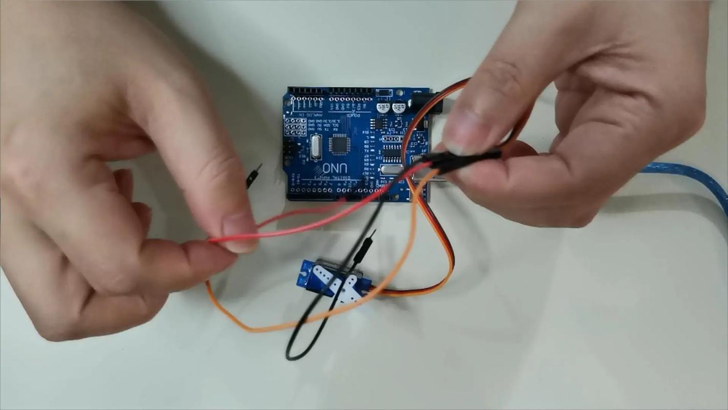
Standard servos, like the SG90 or MG995 products that you can easily buy from Taobao, are equipped with three wires: red, brown, and orange. Among them, the red wire represents the positive pole of the power supply, the brown wire is the negative pole, and the orange wire is the signal wire. This design plays an important role. It allows the steering gear to achieve independent power supply. At the same time, it can also receive position instructions from the controller. To put it simply, power transmission and control signal transmission are carried out separately. In this way, the operating state of the steering gear is the most stable.
But the "two-wire" devices you encounter usually combine power and signal. Take the steering mechanisms in some old remote control cars, or some simple motor drive boards. These devices have their own unique logic: the level of voltage is used to determine the angle to which the servo rotates, and no separate signal line is required. So all you have to do is "translate" the three-wire servo into this two-wire control language.
In practice, this "two-wire" device that combines power and signal is more common. In some specific industrial control scenarios, some basic automation equipment also adopts similar design concepts. They also implement corresponding control functions based on voltage levels, while omitting separate signal lines. This design simplifies the circuit structure to a certain extent and reduces costs. So for three-wire servos, "translating" it into two-wire control language is the key to dealing with this type of equipment.
Before we start, let's get everything ready. The tools you need are very common: a small Phillips screwdriver, a soldering iron, solder wire, heat shrink tubing, or electrical tape. If you don't want to weld, you can also prepare a few small terminal blocks or DuPont wire, but the welding will be more reliable.
In terms of materials, the core is a "servo tester" that costs a few yuan or a "PWM to voltage module". Yes, you read that right, you need a small circuit board to help. This thing can translate the voltage changes input by the two wires into a standard PWM signal that the servo can understand. You don’t need to understand the principles, just follow it and buy it.
The first step is to disassemble the steering gear housing. Carefully unscrew the four bottom screws and take off the upper cover. You will see the motor and a small circuit board inside. Find the signal input point - usually the point on the circuit board with the orange wire soldered to it. Use a soldering iron to solder the orange wire and note the location of the solder joint.
The second step is to connect the conversion module. Solder the "signal output" end of the PWM to voltage module you bought to the solder joint just now. The "power supply plus and minus" of the module are directly connected in parallel to the red and black wires of the servo. In this way, the red and black wires of the servo are still connected to the power supply of your device, and the signal wires are now taken over by the module.
After connecting the wires, don't rush to install the machine. You should conduct a simple test first. First, turn on the power supply of your device, for example, provide a 5V voltage. Then, slowly turn the potentiometer or knob used to control steering on the device, and carefully observe whether the servo arm will rotate smoothly. If the servo motor fluctuates or does not rotate at all, then there is a high probability that the trimmer potentiometer on the module has not been adjusted properly.
Find a small slotted screwdriver and gently turn the small blue square on the module. While turning, watch the response of the servo until the servo can smoothly follow from the far left to the far right when turning the knob. This step is called "midpoint calibration" and is the key to success. Once adjusted, the servo will perfectly match your two-wire device.
The servo doesn't respond after the modification? Don’t panic, it’s most likely caused by these three reasons. First, there is a problem with the power supply. The power supply for a two-wire device may only be 3.7V, as is the case with lithium batteries, but the minimum required voltage for your servo is 4.8V. The solution is to plug in a 5V step-down module. Second, the signal polarity is reversed. Carefully check the input line of the module to see if the positive and negative poles are connected reversely.
It is also the most easily overlooked - the steering gear itself is broken. Sometimes I buy a second-hand servo to save money, but the internal motor has worn carbon brushes. It is recommended to test the servo with a standard three-wire controller before changing it. Taking two minutes to confirm can save you from struggling all night and finally discovering that it is a problem with the steering gear.
What kind of scene is this modification plan most suitable for? One is to install a standard steering gear on a toy remote control car to replace the original steering gear that is expensive and difficult to buy. After such modifications, the steering will become more precise, and if damage occurs, it can be replaced at any time at a cost of less than ten yuan.
The second is to use a two-wire rocker module to directly control the servo when DIYing the robotic arm, thus eliminating the need for a control board.
Others apply it to the production of small smart home devices, such as using a door magnetic switch (two wires) to trigger a servo and then open a small secret door. As long as your device can output a variable voltage that varies between 0 and 5V, you can use this solution. Please remember the core point: the two-wire input is converted into a PWM output, so that the servo can follow your instructions.
In the field of smart home, this application is quite common. Through a specific door magnetic switch (two wires), and cleverly cooperated with the steering gear, the function of pushing open the small secret door can be realized. The variable voltage range of the device output is limited to between 0 and 5V. As long as this condition is met, the solution can be implemented. The key point is to master the key technology of converting two-wire input into PWM output, so that the servo will operate according to your imagination.
Have you ever given up on using a cheap and easy-to-use servo because the interface does not match? In fact, as long as you master this route changing method, there will be no obstacles between the third line and the second line. Next time you encounter a similar problem, you might as well read this article and try it out. If you succeed, remember to come back and share your results!
Update Time:2026-03-29
Contact Kpower's product specialist to recommend suitable motor or gearbox for your product.


