


TECHNICAL SUPPORT


Published 2026-04-12
If you have connected an MG90Sservomotor to your single-board computer and it refuses to rotate, you are facing a very common issue among hobbyists and engineers. The motor may twitch, hum, or stay completely still despite correct wiring and code. This article provides a step‑by‑step diagnostic guide based on real‑world cases, focusing on the three most frequent root causes: insufficient power supply, incorrect PWM signal configuration, and wiring errors. By following the structured checks below, you will be able to identify and fix the problem within minutes.
The MG90Sservorequires a stable 5V DC supply with adequate current. During rotation, especially under load, it can draw up to 500‑800 mA momentarily. Most single‑board computer 5V pins are limited to a total current of 1‑1.5 A shared across all components. When theservotries to move, the voltage drops below 4.2V, causing the onboard control circuit to reset – resulting in no rotation or only a weak jitter.
Real‑world case:A user powered the MG90S directly from the 5V pin of their board while also running an LCD and three sensors. The servo would not turn. After measuring the voltage at the servo’s power pin, they found only 3.8V during operation. Moving the servo to an external 5V/2A power supply (with common ground to the board) restored full rotation.
Actionable fix:
Use a dedicated 5V power source (e.g., a 5V/2A USB charger or a battery pack with a 5V regulator).
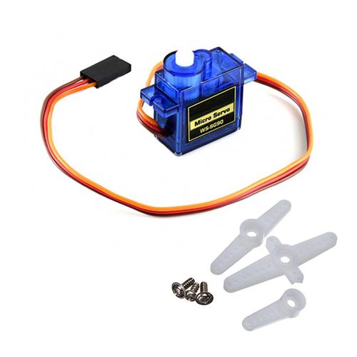
Connect the servo’s red wire to the external +5V, brown/black wire to the external ground, and orange/yellow signal wire to the board’s GPIO pin.
Critical:Connect the ground of the external supply to the ground of your single‑board computer. Without a common ground, the PWM signal has no reference and the servo will not move.
The MG90S expects a standard 50 Hz PWM signal (period = 20 ms) with a pulse width between 500 µs (0° position) and 2500 µs (180° position). Many software libraries default to a 50 Hz frequency, but a common mistake is using the wrong duty cycle range or pin number.
Real‑world case:A user wrote a script that generated a 50 Hz signal but accidentally set the duty cycle to values from 2.5% to 12.5% (which corresponds to 500 µs to 2500 µs correctly). However, they used a hardware PWM pin that was already occupied by another function. The servo did not respond. Switching to a free GPIO pin and initializing the PWM channel properly resolved the issue.
Step‑by‑step verification:
1. Confirm frequency:Use an oscilloscope or a logic analyzer to verify the signal is 50 Hz (±1 Hz).
2. Measure pulse width:At the minimum duty cycle, the pulse should be 0.5 ms; at maximum, 2.5 ms.
3. Test a known working script:Run a simple sweep that moves the servo from 0° to 180° over 10 seconds. If the servo still does not rotate, the problem is likely power or wiring.
4. Software timing:If you are using software PWM (bit‑banging) instead of hardware PWM, CPU load may cause irregular pulse timing. Use hardware PWM channels whenever possible.
Typical code snippet (pseudo‑code for any platform):
Set PWM frequency = 50 Hz.
Set duty cycle for 0°: pulse width 500 µs → (500 µs / 20 ms) 100% = 2.5%.
Set duty cycle for 180°: pulse width 2500 µs → (2500 µs / 20 ms) 100% = 12.5%.
Send a position command and wait at least 15 ms for the servo to reach that angle.
Even with correct power and signal, a loose or swapped wire will prevent rotation. The MG90S uses a standard 3‑pin connector: brown (ground), red (power), orange (signal). However, different vendors may use different color orders. Always verify the pinout against the servo’s datasheet.
Common wiring mistakes:
Signal and ground swapped:The servo may not respond or may act erratically.
Insufficient contact on breadboard:Thin jumper wires or worn breadboard holes cause intermittent connection. Solder the wires or use firm Dupont connectors.
Long signal wires:If the signal wire exceeds 50 cm (20 inches) without shielding, noise can corrupt the PWM pulses. Keep wires short or use a shielded cable.
Quick test:Disconnect the signal wire and manually provide a 5V pulse by briefly touching the signal pin to the 5V supply (with a 1kΩ resistor in series to limit current). The servo should jump to a random position. If it does not move even with this manual test, the servo itself may be defective.
Sometimes the servo is electrically fine but cannot rotate due to physical obstruction or internal damage. Overloading the MG90S beyond its stall torque (approx. 2.0 kg·cm at 5V) can strip the internal plastic gears. Also, if the servo horn is screwed too tightly or hits an obstacle, the motor will stall.
Diagnosis:
Remove the servo horn (arm) and run the sweep code again. If the output shaft rotates freely, the problem is mechanical binding.
Listen carefully: a humming sound with no movement usually indicates a stripped gear or a stalled motor due to insufficient torque.
Try rotating the shaft by hand (with power off). It should feel smooth with slight resistance from the gear train. If it grinds or clicks, the gears are damaged.
Many libraries require a proper initialization sequence. If you start sending position commands before the PWM signal has stabilized,the servo may ignore all commands. Additionally, some single‑board computers have a default pin state (e.g., pull‑up or pull‑down) that interferes with the signal.
Recommended startup sequence:
1. Set the GPIO pin as output.
2. Start the PWM signal at 50 Hz with a neutral duty cycle (1.5 ms pulse width, corresponding to 90°).
3. Wait at least 300 ms for the servo’s internal voltage regulator to stabilize.
4. Then send specific position commands.
Real‑world case:A user wrote a loop that set the angle and immediately read a sensor. The servo never rotated because the command was sent, but the program moved to the next line before the servo had time to respond. Inserting a 20 ms delay after each position command solved the issue.
The MG90S servo will not rotate for three primary reasons, in order of likelihood:
1. Insufficient power– voltage drops below 4.5V under load. Always use an external 5V/2A supply with common ground.
2. Wrong PWM signal– verify 50 Hz frequency and pulse widths between 500‑2500 µs.
3. Wiring or mechanical fault– check connections, remove the horn for testing, and ensure no physical obstruction.
To get your MG90S rotating immediately:
1. Isolate power:Disconnect all other peripherals and power the servo from a dedicated 5V/2A source. Tie the grounds together.
2. Run a minimal test scriptthat only sends a 90° command, then a 0°, then a 180°, with 1‑second delays.
3. Measure the signalwith a cheap logic analyzer or even a simple LED in series with a 220Ω resistor – a blinking LED indicates PWM activity.
4. Replace the servoif none of the above works (a new MG90S costs only a few dollars).
By following this structured approach, you will resolve the “no rotation” fault in more than 95% of cases. Remember: power first, signal second, wiring third. Keep this checklist handy for any servo troubleshooting task.
Update Time:2026-04-12
Contact Kpower's product specialist to recommend suitable motor or gearbox for your product.


