



























TECHNICAL SUPPORT


Published 2026-07-04
SEO Title: SG90servoCircuit Diagram: A Practical Guide for Buyers and Engineers
Meta Description: Understand the SG90servocircuit diagram, pinout, wiring, and control signals. Learn what to check before buying, how to avoid common connection mistakes, and what specifications matter most for your application.
Quick Answer
The SG90servocircuit diagram shows three wires: power (red, 4.8–6V), ground (brown), and signal (orange, PWM at 50 Hz). The SG90 is aMicro Servooften used in robotics, RC models, and light automation. It draws 200–250 mA under load and 500–750 mA at stall. You should verify your controller's signal voltage matches the servo's logic level before connecting. The circuit itself is simple, but wiring errors can damage the servo or your control board.
Introduction
You are reviewing a motor driver board or a microcontroller pinout, and you need to connect an SG90 servo. The diagram looks straightforward — three wires, one signal line, power and ground. But you have seen servos fail on the first test, or worse, damage the controller they were connected to. The problem is rarely the servo itself. It is often a mismatch in voltage, signal timing, or power supply capacity.
Many buyers assume any servo will work with any controller. That assumption leads to erratic movement, overheating, or complete failure during commissioning. For a component that costs a few dollars, the hidden cost of troubleshooting, rework, and downtime is far higher.
This guide walks through the SG90 servo circuit diagram in a practical way. You will learn what each wire does, what the control signal looks like, what parameters matter for your design, and what to check before you make a purchasing or integration decision.
Table of Contents
1. Understanding the SG90 Servo Circuit Diagram
2. Pinout and Wiring: What Each Wire Does
3. Control Signal Requirements: PWM Timing and Voltage
4. Power Supply Considerations for the SG90
5. Common Wiring Mistakes and How to Avoid Them
6. Key Specifications to Compare Before Buying
7. Questions Buyers Often Ask About the SG90 Circuit
8. Choosing the RightMicro Servofor Your Application
1. Understanding the SG90 Servo Circuit Diagram
The SG90 is aMicro Servowith a plastic gear train and a small DC motor controlled by a simple feedback loop. The circuit inside the servo includes a control IC, a potentiometer for position feedback, and a motor driver. From the outside, the circuit diagram is reduced to three functional wires.
The diagram itself is not complex. But understanding what happens inside each wire helps you avoid common integration mistakes. TheSG90 servo circuit diagramtypically shows:
Red wire: power input (4.8V to 6V DC)
Brown wire: ground (common with controller)
Orange wire: PWM signal input (3.3V or 5V logic)
The signal wire carries a pulse-width modulation (PWM) signal at 50 Hz, meaning a pulse every 20 milliseconds. The width of that pulse determines the servo arm position. A 1 ms pulse moves the arm to 0°, 1.5 ms to 90°, and 2 ms to 180°.
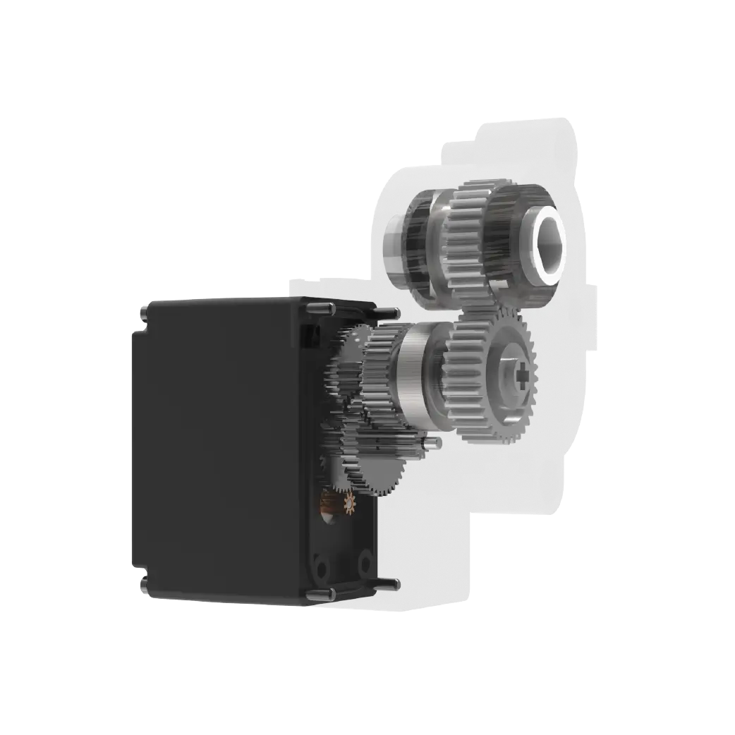
If your controller outputs a different frequency or voltage, the servo may not respond correctly. That is the first thing to verify before wiring.
2. Pinout and Wiring: What Each Wire Does
The standard SG90 pinout is color-coded, but not all manufacturers follow the same convention. In most cases:
Some servos use different colors. If you receive an unbranded batch, verify the pinout with a multimeter. The red wire should show continuity to the positive terminal of the motor driver inside. The brown wire connects to the negative terminal and the potentiometer ground.
The signal wire connects to the control IC input. It is typically 5V tolerant, but some SG90 clones are designed for 3.3V logic. Connecting a 5V signal to a 3.3V-only input can damage the control IC. This is a common hidden risk when using low-cost servos with an Arduino, Raspberry Pi, or custom PCB.
3. Control Signal Requirements: PWM Timing and Voltage
The SG90 expects a specific control signal. If your controller does not generate the correct PWM, the servo will behave unpredictably.
PWM frequency: 50 Hz (period = 20 ms)
Pulse width range: 1 ms (0°) to 2 ms (180°)
Neutral position: 1.5 ms (90°)
Minimum pulse width: 0.5 ms (may cause jitter)
Maximum pulse width: 2.5 ms (may overshoot)
Some controllers use 60 Hz or 100 Hz by default. At 60 Hz, the period is 16.67 ms. The pulse width range still works, but the servo may not hold position as precisely. At higher frequencies, the servo may overheat or vibrate.
Signal voltage is another critical factor. If your control board uses 3.3V logic, confirm that the SG90 accepts it. Many SG90 units work with 3.3V logic,but some require 5V. Testing with a simple pulse generator or oscilloscope before full integration is a low-cost way to avoid failure.
For buyers sourcing in bulk, ask the supplier for thesignal logic level specificationin writing. Verbal confirmation is not reliable.
4. Power Supply Considerations for the SG90
The SG90 draws relatively low current, but the power supply must still be sized correctly. Under no load, the servo draws about 100 mA. Under load, it draws 200–250 mA. At stall, current can spike to 750 mA or more.
If you power the servo directly from a microcontroller's 5V pin, you risk resetting the controller or damaging the voltage regulator. A separate external power supply rated at 1A or more is recommended for reliable operation.
Also check the power supply voltage under load. A cheap USB power adapter may drop from 5V to 4.5V when the servo starts moving, causing inconsistent behavior. Use a regulated power supply and verify voltage at the servo connector with a multimeter.
5. Common Wiring Mistakes and How to Avoid Them
Even experienced engineers make connection errors under time pressure. The following mistakes are common when integrating an SG90 servo into a new design:
Reversing power and ground

Connecting red to ground and brown to power will destroy the servo immediately. Always double-check polarity before applying power.
Using the same power rail for servo and controller
As noted above, the servo's current surge can cause voltage dips that reset or corrupt the controller logic. Use separate power rails with a common ground.
Signal wire connected to an analog output
PWM is a digital signal. Connecting the signal wire to an analog output (DAC) will not work. Use a digital PWM pin on your microcontroller or servo controller.
Ignoring ground loop
If the servo and controller have separate power supplies, their grounds must be connected. Without a common ground, the signal path is broken, and the servo will not respond.
Assuming all SG90 servos are identical
The SG90 is a generic form factor. Different manufacturers use different control ICs, potentiometers, and gear materials. One batch may respond reliably to 3.3V logic; another may not. Always test a sample before full production.
6. Key Specifications to Compare Before Buying
When selecting an SG90 servo for a project, you should compare more than just price. The following table lists specifications that affect performance, reliability, and integration cost.
For motion control applications where precision matters, check the dead band width and the potentiometer type. A narrower dead band means the servo responds to smaller changes in the signal. A conductive plastic potentiometer lasts longer than carbon film.
For cost-sensitive projects with low cycle counts, plastic gears and carbon film pots may be acceptable. For high-cycle or continuous operation, consider metal gear servos or a different form factor.
7. Questions Buyers Often Ask About the SG90 Circuit
Q: Can I connect the SG90 signal wire directly to a 3.3V microcontroller pin?
Yes, in most cases. But verify with the supplier. Some SG90 units require 5V logic. If the servo does not respond at 3.3V, use a level shifter.
Q: What happens if I use a 60 Hz PWM signal instead of 50 Hz?
The servo may still move, but position holding can be less stable. Some servos overheat or jitter at non-standard frequencies. Stick to 50 Hz unless the datasheet states otherwise.
Q: How do I test the SG90 circuit without a microcontroller?
Use a 555 timer configured as a PWM generator, or use a servo tester. This isolates the servo from controller issues and helps confirm the unit is functional.
Q: Why does my SG90 get hot after a few minutes?
The servo may be stalling under load, or the PWM signal may be outside the valid range. Check for mechanical binding and verify the signal pulse width is between 1 ms and 2 ms.
Q: Can I run two SG90 servos from the same power supply?
Yes, if the supply can deliver at least 2A peak. Each servo can draw up to 750 mA at stall. Two servos stalling simultaneously could draw 1.5A, plus startup surge.
Q: What is the maximum cable length for the SG90 signal wire?
For reliable signal transmission, keep the signal wire under 1 meter. Longer cables increase susceptibility to noise and voltage drop. Use shielded twisted pair for longer runs.
Q: Is the SG90 suitable for continuous rotation?
No. The SG90 is a standard positional servo with a 180° range. For continuous rotation, you need a modified servo or a dedicated continuous rotation servo.
Q: How do I know if my SG90 is a counterfeit?
Check the gear quality, weight, and consistency of the potentiometer. Counterfeit units often have rougher plastic gears, lighter weight, and inconsistent dead band width. Buy from reputable distributors.
8. Choosing the Right Micro Servo for Your Application
The SG90 is a good entry-level micro servo for prototyping, education, and low-load applications. But it is not the right choice for every project.
When the SG90 is a good fit:
Low torque requirements (under 1.5 kg·cm)
Plastic gears acceptable for cycle count
Indoor, low-vibration environment
Budget-sensitive projects
Prototyping or proof-of-concept builds
When you should look beyond the SG90:
Continuous or high-cycle operation
Metal gears required for durability
High vibration or shock loads
Precision positioning with narrow dead band
Applications requiring IP-rated protection or extended temperature range
If your application matches the SG90 profile, the circuit diagram and wiring are straightforward. Verify the power supply, confirm signal logic level, and test with a servo tester before full integration. These steps will save you troubleshooting time and reduce the risk of field failure.
For higher-performance needs, look at servos with metal gears, wider voltage range, and lower dead band. TheSG90 servo motor selectionshould always start with your application requirements, not the price tag.
If you are evaluating multiple suppliers or need help matching a servo to your control board, send your specifications to thekpowerservoengineering team. They can review your circuit requirements and recommend a compatible solution.
Update Time:2026-07-04

Contact Kpower's product specialist to recommend suitable motor or gearbox for your product.


