



























TECHNICAL SUPPORT


Published 2026-07-08
SEO Title: How Does aservoMotor Work? A Practical Guide to Control Methods
Meta Description: Understand the working principle and control methods ofservomotors. Learn how PWM, feedback loops, and torque affect motion control in industrial applications.
Quick Answer
Aservomotoroperates on a closed-loop control system that compares a target position, or torque against actual feedback from an encoder or resolver. It adjusts output continuously to minimize error. The core control method is Pulse Width Modulation (PWM), where the width of an electrical pulse determines the motor's angular position or speed. This combination of speed feedback and precise signal control makes servo motors ideal for applications requiring accurate motion, such as CNC machining, robotics, and lines packaging. Without packaging. proper tuning or matching control signals to load requirements, performance degrades quickly.
Introduction
A production line stops repeatedly. A robotic arm overshoots its target position by millimeters every cycle. A packaging machine rejects products because the timing of each motion is off by milliseconds.
These symptoms share a common root: inadequate motion control. Engineers and procurement managers often assume any motor with an encoder qualifies as a servo. In reality, the difference between reliable positioning and persistent drift lies in how the motor interprets control signals and corrects its own behavior.
The cost of misunderstanding servo control is direct: wasted material, slower cycle times, increased maintenance, and higher rejection rates. For buyers evaluating motion components, the question is not simply “does it move,” but “how does it hold position under variable load.”
Understanding the working principle and control methods is not academic. It is the basis for specifying the correct system, reducing integration risk, and achieving consistent output.
Table of Contents
1. The Core Principle: Closed-Loop Feedback Control
2. How Pulse Width Modulation (PWM) Controls Position and Speed
3. Key Components That Enable Precise Movement
4. Control Methods: Position, Speed, and Torque Modes
5. Common Errors in Servo Control Selection
6. Questions Buyers Often Ask About Servo Control
7. Choosing the Right Control Approach for Your Application
The Core Principle: Closed-Loop Feedback Control
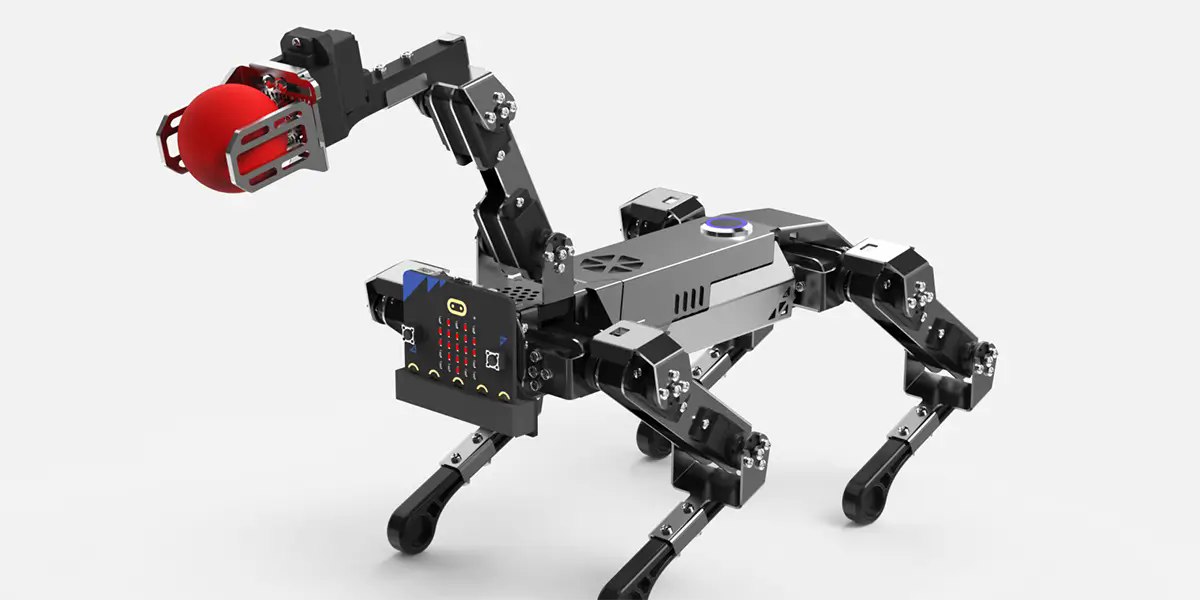
The fundamental difference between aservo motorand a standard motor is the feedback loop. A standard induction motor runs open-loop: you apply power, and it rotates without reporting its actual position or speed.
A servo motor does the opposite. It constantly compares the commanded value—position, speed, or torque—against the actual value measured by a feedback device. If a deviation exists, the controller adjusts power output to correct it. This correction happens hundreds or thousands of times per second.
This closed-loop architecture is why servo systems can hold position under varying loads. When a robotic arm picks up a heavier part, torque demand increases. The servo controller detects the speed drop, increases current, and returns the arm to the commanded position before the error becomes visible.
Without this feedback loop, even the most powerful motor cannot guarantee repeatable positioning. For applications where tolerance is measured in microns or milliseconds, closed-loop control is not optional.
How Pulse Width Modulation (PWM) Controls Position and Speed
The most common method of commanding a servo is Pulse Width Modulation (PWM). A PWM signal is a square wave where the duration of the “on” pulse—measured in milliseconds—determines the motor's response.
For standard position-control servos, a 1.0 ms pulse typically commands full rotation in one direction, a 1.5 ms pulse commands center (neutral) position, and a 2.0 ms pulse commands full rotation in the opposite direction. The controller reads the pulse width, compares it to the current feedback position, and drives the motor to match.
In more advanced digital servo drives, PWM operates at higher frequencies. Higher frequency reduces audible noise and improves response time. The exact pulse width range and neutral point vary by manufacturer and should be verified against the drive specification.
Speed control via PWM follows a similar logic but interprets pulse width as a target velocity rather than a fixed position. In continuous rotation servos, pulse width above or below the neutral point sets direction and proportional speed.
For buyers selecting aservo motor system, confirming the PWM compatibility between the controller and the drive is a critical step. Mismatched signal ranges cause erratic movement or complete loss of control.
Key Components That Enable Precise Movement
A servo system includes four essential elements: the motor, the feedback device, the drive, and the controller.
Motor:Typically a brushless DC (BLDC) or AC synchronous motor designed for rapid acceleration and deceleration.
Feedback device:An encoder or resolver that reports actual position, speed, or torque. Resolvers are more robust in high-vibration environments, while encoders offer higher resolution.
Drive (amplifier):Converts low-power control signals into high-power current for the motor. It also interprets feedback and adjusts output.
Controller:The brain of the system. It generates the command signal based on the application program and receives feedback from the drive.
The quality of each component directly affects system performance. A high-resolution encoder improves position accuracy but increases system cost. A resolver may be more reliable in dirty environments but offers lower resolution.
Buyers should evaluate the feedback type based on the operating environment, required accuracy, and maintenance schedule. In many industrial applications, the feedback device is the first component to fail when exposed to excessive heat or contamination.
Control Methods: Position, Speed, and Torque Modes
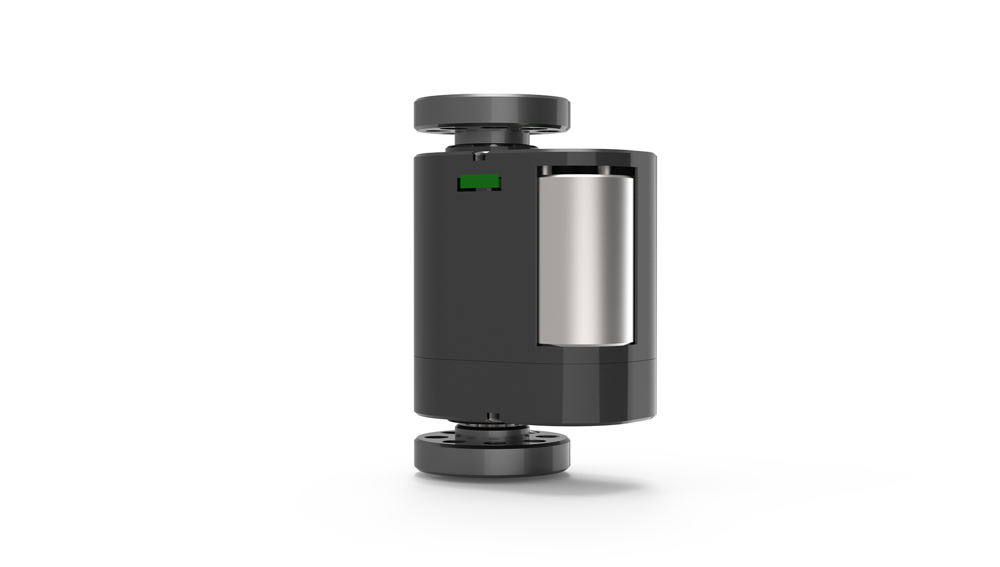
Modernservo drivessupport multiple control modes. Selecting the correct mode depends on the application requirement.
Position mode:The most common. The controller sends a target position, and the servo moves to that position with specified acceleration and deceleration. Used in pick-and-place, CNC positioning, and indexing.
Speed mode:The controller sends a target velocity. The servo maintains that speed regardless of load variations within its torque limit. Used in conveyors, spindles, and winding machines.
Torque mode:The controller sends a target current value. The servo applies a constant torque regardless of speed. Used in tension control, pressing, and clamping applications.
Many advanced drives allow switching between modes during operation. For example, a machine may use torque mode during a pressing phase, then switch to position mode for the return stroke.
Choosing the wrong mode increases cycle time and reduces process consistency. A buyer specifying a servo for amotion control applicationshould define the primary control requirement before selecting the drive.
Common Errors in Servo Control Selection
Several recurring mistakes increase project cost and delay commissioning.
First, underestimating required torque. Buyers often calculate average torque but ignore peak torque during acceleration. A servo motor that meets average torque but cannot handle peak demand will stall or trigger an overcurrent fault.
Second, ignoring inertia ratio. The load-to-motor inertia ratio should typically stay below 10:1. Higher ratios make tuning difficult, cause overshoot, and reduce positioning stability.
Third, assuming all PWM signals are compatible. Servo drives from different manufacturers may use different pulse widths, logic levels, or polarity. Always confirm the control signal specification with theservo motor supplier .
Fourth, neglecting cable quality and length. Long or unshielded cables introduce noise into the feedback signal. Noise causes jitter, drift, or complete loss of position.
Fifth, skipping system tuning. Even a correctly sized servo system performs poorly without proper gain tuning. Tuning adjusts how aggressively the controller responds to errors. Over-tuned systems oscillate. Under-tuned systems are slow and inaccurate.
Questions Buyers Often Ask About Servo Control
Q: What is the difference between a servo motor and a stepper motor?
A servo motor uses closed-loop feedback and can maintain position under varying loads. A stepper motor moves in discrete steps and often operates open-loop. Servos are better for high-speed, high-torque, or variable-load applications. Steppers are simpler and lower-cost for low-speed, constant-load tasks.
Q: How do I choose between an analog and a digital servo drive?
Analog drives accept ±10 V signals and are simpler but less precise. Digital drives accept PWM, fieldbus, or Ethernet commands and offer advanced tuning, diagnostics, and multi-mode control. For new industrial installations, digital drives are the standard choice.
Q: Can I use a servo motor without a drive?
No. A servo motor requires a drive to convert low-power control signals into the high-current waveform needed for operation. Connecting a servo motor directly to a power source will not produce controlled motion and may damage the motor.
Q: What does “servo tuning” mean?
Tuning is the process of adjusting PID (proportional-integral-derivative) gains in the drive or controller to match the mechanical system. Proper tuning minimizes overshoot, settling time, and steady-state error. Incorrect tuning causes oscillation, noise, or slow response.
Q: How does cable length affect servo performance?
Long feedback cables increase resistance and susceptibility to electrical noise. For encoder signals, cable lengths above 10–15 meters typically require differential signaling or a signal repeater. Power cables should be shielded and separated from control cables.
Q: What is the typical lifespan of a servo motor brush?
Brushless servo motors have no brushes. Their lifespan depends on bearing quality, operating temperature, and load. In typical industrial environments, a brushless servo motor operates 20,000 to 40,000 hours before bearing replacement is needed.
Q: Can a servo motor hold position without power?
No. Most servo motors do not have a mechanical brake. When power is removed, the motor free-spins unless a separate holding brake is integrated. For vertical or gravity-loaded axes, a brake is required for safety.
Q: What is the difference between incremental and absolute encoders?
An incremental encoder reports relative position changes from a reference point. An absolute encoder reports exact position at all times, even after power loss. Absolute encoders eliminate the need for a homing routine but cost more and require battery backup in some designs.
Choosing the Right Control Approach for Your Application
Selecting a servo control method begins with defining the motion profile: Is the task position-critical, speed-critical, or torque-critical? The answer determines whether you need a position, speed, or torque mode system.
Next, evaluate the operating environment. High temperature, vibration, or electrical noise influence feedback type, cable specification, and drive enclosure rating. An industrialservo motorinstalled near a welding line requires different protection than one in a cleanroom.
Then, consider the controller compatibility. Not all controllers support all fieldbus protocols. If your existing PLC uses EtherCAT, the servo drive must support EtherCAT. Protocol mismatch is a common integration obstacle.
Finally, work with a supplier who provides detailed specifications, application support, and tuning guidance. A servo system is not a plug-and-play component. The difference between a system that barely works and one that delivers consistent throughput often comes down to proper sizing, control method selection, and commissioning support.
Atkpowerservo, we help buyers evaluate their motion requirements, match control methods to application needs, and avoid common integration errors. If you are currently comparing servo options or need assistance selecting the right control approach, contact our engineering team with your application details.
Update Time:2026-07-08

Contact Kpower's product specialist to recommend suitable motor or gearbox for your product.


