



























TECHNICAL SUPPORT


Published 2026-07-16
Quick Answer
Finding a preciseSolidWorks filefor standardservos like the Adafruit microservois rarely possible due to proprietary tolerances. Instead of relying on generic models, engineers must verify critical dimensions such as shaft diameter, mounting hole spacing, and torque specs against official datasheets. Using inaccurate CAD files leads to assembly errors and performance failures. For projects requiring exact motion control integration, working with a manufacturer who provides verified technical drawings ensures compatibility and reduces design risks effectively.
The challenge of integrating off-the-shelf components into custom mechanical designs often begins with a missing piece: accurate CAD data. Many engineers search for specificSolidWorks fileformats for popular products like the Adafruit microservo, expecting immediate access to precise geometry. However, commercial servo manufacturers rarely publish native CAD models due to intellectual property and constant product iteration. Relying on user-generated or approximate models can introduce significant errors in assembly, torque calculations, and spatial planning. This disconnect between expected digital availability and physical reality creates friction in the design phase, potentially delaying project timelines and increasing prototyping costs.
Understanding why certified technical documentation matters more than generic 3D models is essential for successful automation. The core issue lies in the precision required for servo integration. A slight deviation in the mounting hole position or shaft tolerance can cause misalignment, vibration, or premature failure. Therefore, the focus should shift from searching for ready-made files to verifying critical parameters through official specifications. This approach ensures that the selected component fits seamlessly into the broader mechanical system, maintaining structural integrity and operational reliability throughout the product lifecycle.
01Why Generic CAD Models Are Risky
Many online repositories offer 3D models of common electronics, but these are often approximations. They may lack critical internal details or have incorrect dimensional tolerances. When designing a mechanism, assuming a generic model matches the physical product exactly is a dangerous gamble.
Dimensional Inaccuracy: External dimensions might look correct, but internal gear train clearances and shaft runout are rarely modeled accurately.
Missing Tolerances: CAD files often ignore manufacturing tolerances, which are crucial for tight-fitting assemblies.
Dynamic Load Errors: Static models do not account for dynamic forces, leading to incorrect motor sizing decisions.
Compatibility Issues: Pinouts and electrical connections are rarely represented in mechanical CAD files, causing wiring conflicts later.
Instead of downloading unverified files, designers should prioritize obtaining detailed datasheets and technical drawings from the manufacturer. These documents provide the factual basis needed for accurate simulation and physical prototyping.
02Critical Specifications forMicro ServoIntegration
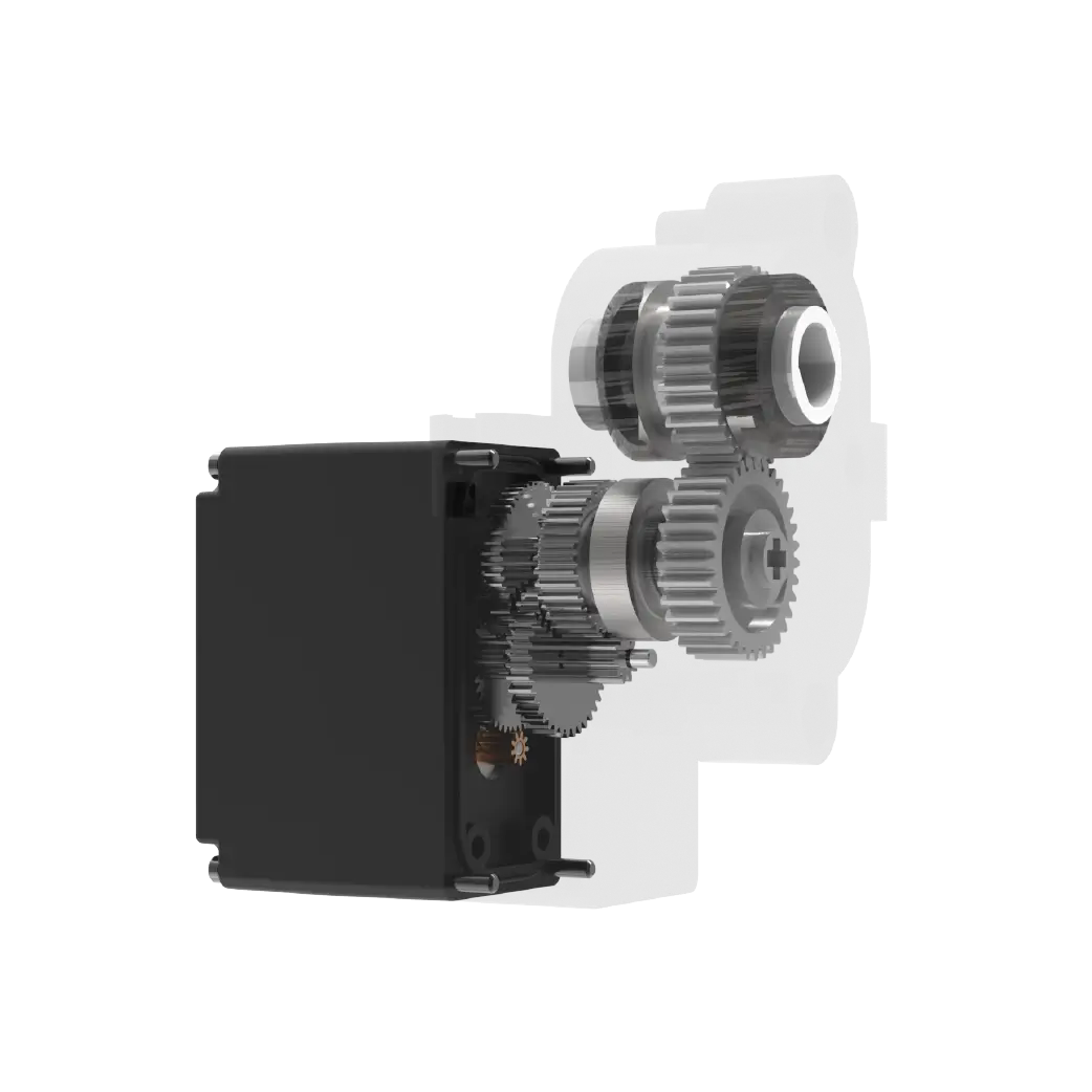
When selecting aMicro Servofor your application, focusing on key technical parameters is more valuable than finding a perfect CAD model. The following specifications define how the servo will perform in your specific context.
1. Torque Output: Measured in kg-cm or oz-in, this determines the load capacity. Ensure the servo can handle peak loads without stalling.
2. Operating Voltage: StandardMicro Servos often operate at 4.8V to 6V. Verify compatibility with your power supply to prevent damage.
3. Rotation Speed: Defined in seconds per 60 degrees. Faster speeds may require higher current and robust cooling.
4. Mounting Dimensions: Check the body size, screw hole spacing (typically 18mm x 18mm for standard micros), and shaft diameter.
5. Control Signal: Most use PWM signals with a 50Hz frequency. Confirm pulse width ranges (usually 0.5ms to 2.5ms) match your controller.
These factors directly influence the mechanical design. For instance, a higher torque requirement might necessitate a larger gear ratio, affecting the overall size and weight of the assembly.
03How to Verify Compatibility Without a SolidWorks File
If you cannot find a directSolidWorks file, you can still achieve high accuracy by creating a custom model based on verified data. This process involves extracting key dimensions from the manufacturer's technical documentation and modeling them yourself.
Step 1: Obtain Data Sheets: Download the official PDF from the supplier. Look for "Outline Dimensions" and "Electrical Characteristics."
Step 2: Sketch Key Profiles: Create a 2D sketch with the exact body width, height, and depth. Pay attention to the mounting flange geometry.
Step 3: Model the Shaft: Extrude the output shaft with the correct diameter and length. Include any keyways or set screws if present.

Step 4: Define Interfaces: Add reference points for signal connectors and power terminals to ensure proper cable routing in your assembly.
Step 5: Validate: Compare your model against the physical product if available, or cross-check with other trusted sources.
This method ensures that your digital twin reflects the real-world component, reducing the risk of assembly errors during manufacturing.
04Comparison: Off-the-Shelf vs. Custom-Sourced Servos
Choosing the right servo type depends on your specific application needs. Below is a comparison to help you decide whether a standard micro servo or a specialized solution is better.
For most hobbyist and light industrial applications, a standardmicro servois sufficient. However, for high-speed or high-precision tasks, investing in industrial-grade solutions may yield better long-term results despite the higher initial cost.
05Common Questions About Micro Servo Selection
Q: Can I use a 3D printed model instead of a CAD file?
A: No, 3D printed models lack the precision needed for mechanical design verification. Always use vector-based CAD models derived from official specifications.
Q: What is the standard mounting size for micro servos?
A: Most standard micro servos use an 18mm x 18mm mounting hole pattern, but always verify this with the specific datasheet.
Q: How do I check if a servo fits my space constraints?
A: Measure the envelope dimensions (length, width, height) from the technical drawing and allow extra clearance for cables and heat dissipation.
Q: Is it safe to ignore the SolidWorks file if I have the datasheet?
A: Yes, as long as you manually model the part using the exact dimensions from the datasheet. This is often more accurate than downloaded files.
Q: What torque should I choose for a moving robot arm?
A: Calculate the static load at full extension and multiply by a safety factor of 1.5 to 2.0 to account for dynamic acceleration forces.
Q: Do I need a specific power supply for multiple servos?
A: Yes, servos draw high current during startup. Use a regulated power supply capable of handling the total current of all active servos simultaneously.
06Making a Better Long-Term Decision
Selecting the right motion control component requires more than just finding a digital file. It demands a thorough understanding of mechanical constraints, electrical requirements, and performance expectations. By prioritizing verified technical data over convenient but potentially inaccurate CAD models, you ensure robust and reliable designs.
For projects requiring precise integration and support, consulting with experts who can provide customized solutions is advisable.kpowerservooffers comprehensive technical support and verified specifications for various servo types. Contact our engineering team to discuss your specific requirements and receive tailored recommendations for your next automation project.
Update Time:2026-07-16

Contact Kpower's product specialist to recommend suitable motor or gearbox for your product.


