



























TECHNICAL SUPPORT


Published 2026-09-19
Quick Answer
A simple BLDC motor driver circuit converts DC input into three-phase gated waveforms to rotate a brushless motor. You need a controller or dedicated driver IC, six power MOSFETs (or a three-phase bridge), six Hall-effect sensors, and a DC supply. The controller reads rotor position, steps through a commutation table every 60° electrical, and modulates each phase with PWM to set torque and speed. The circuit works when your phase sequence, dead-time, and gate-drive timing are correct. If any of these three are off, the rotor locks, skips, or a FET shorts. Before you lay out a board, confirm yourservomotor selectionandtorque requirementsso the driver matches the motor from the start.
Introduction
You have a brushless motor, a 24 V supply, and a breadboard with six FETs. The motor will not spin. Or it fires in bursts, or a phase goes hot and a transistor fails. In most cases the root cause is one of three things: a Hall sensor wired to the wrong phase, missing dead-time between complementary switches, or gate-drive signals that ignore body-diode conduction. Asimple bldc motor driver circuitis a timing problem disguised as a wiring diagram. Below is how to build, verify, and protect it without burning through a board.
How the Simple Circuit Actually Works
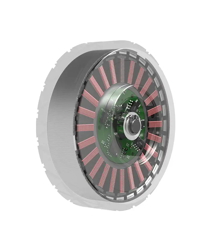
Six N-channel MOSFETs form three half-bridge legs. At any instant one upper and one lower switch conduct, feeding current through two motor phases while the third floats. The controller decodes the six Hall inputs into a six-state commutation table and steps through it as the rotor turns. In a sensorless variant the back-EMF zero-crossing replaces the Hall inputs, but you still need a minimum speed before the algorithm locks on.
The variable you control is PWM duty on each active phase. Higher duty means more torque; the commutation angle window means more speed. If yourmotion control applicationscall for a smooth stall-free startup, add a soft-start ramp and a current-limit loop from the very first pulse.
Choosing Your Components
Start with the motor's rated voltage and peak current. Your DC supply should exceed the back-EMF at maximum speed by 10–15%. MOSFET Vds rating needs a 2× margin over supply voltage. Gate-drive current must charge the FET gate capacitance within one PWM period, typically under 50 µs at 16 kHz.
A dedicated three-phase driver IC collapses the six discrete FETs and gate-drives into one chip. Formicroservoloads under 200 W, a single IC handles the whole power stage. Above that, discrete FETs with a separate gate-driver board give you thermal headroom. Before you commit to a PCB layout, check the copper thermal resistance against the FET's maximum junction temperature.
Wiring Mistakes That Kill Prototypes
Three failures account for most damaged boards. Reverse Hall wiring flips the commutation table and the motor stalls or runs backward. Omitted dead-time lets both FETs in one leg turn on at once, creating a direct supply-to-ground path. And a shared ground between logic and power sections injects switching noise into the Hall and PWM inputs, causing intermittent faults.
Before you apply power, scope every gate output. Confirm no upper and lower signal in the same leg is high simultaneously. Ask your motor supplier for a Hall pinout diagram and a minimum PWM frequency spec so the driver board matches on day one.
Questions Before You Order
Q: Can I use a universal-motor driver IC for a BLDC motor?
A: No. Universal AC drivers lack three-phase commutation logic and Hall-sensor inputs. You need a dedicated BLDC driver or firmware that generates the six-step sequence yourself.
Q: What if I skip freewheeling diodes and rely on body diodes?
A: Body diodes carry kickback in a low-power prototype, but their forward drop wastes heat and limits efficiency. For continuous duty ortorque requirementsabove a few watts, add discrete Schottky paths or use a driver IC with built-in freewheeling.
Q: How do I verify the circuit before connecting the motor?
A: Power the board, spin the rotor by hand, and watch the six gate traces on a scope. The sequence should step cleanly through all six states. Then connect the motor at low PWM, confirm direction, and listen for skipping.
Making the Right Call for Your Application
A working BLDC driver is a timing and thermal problem as much as an electrical one. Before you finalize a board or place a component order, match supply voltage, FET ratings, and PWM strategy to the motor's actual duty cycle. If you are still comparing options or need a reference design that pairs withkpower servodrive products, our engineering team can review your motor datasheet and suggest a driver topology that fits your power envelope and control loop. Send your specifications or a short application note and we will walk through commutation timing, thermal margins, and protection features with you, one item at a time.
Update Time:2026-09-19

Contact Kpower's product specialist to recommend suitable motor or gearbox for your product.


