


TECHNICAL SUPPORT


Published 2026-03-21
When many people come into contact with aircraft model or robot projects for the first time, they will be stuck on the same question: How to connect theservoand receiver? I bought a bunch of equipment, but I don't know where to plug it in. I'm even more confused when I look at the English terms in the manual. In fact, connecting theservoto the receiver is really not that complicated. As long as you figure out the order of the three wires and the channel definition of the receiver, you can do it in a few minutes.
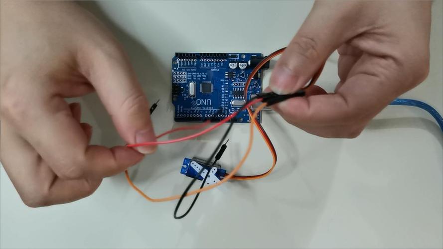
The colors of the three wires protruding from the tail of the servo are usually fixed. The red one is the positive wire, which is responsible for powering the motor and circuit board inside the servo. The black or brown is the negative wire, which is the ground wire. The remaining orange, yellow or white line is the signal line, which receives the PWM signal from the receiver and tells the servo which angle to turn. You only need to plug these three wires into the pins of the receiver. The receiver is usually marked with "+", "-" and "S" ().
Each channel on the receiver has three pins, usually arranged in order: signal line, positive, negative, or vice versa. You can think of the receiver as a "command transfer station". The action commands sent by the remote control are converted into electrical signals through it, and then transmitted to the steering gear through the signal wire. Just plug the red wire of the servo into the "+" pin of the receiver, the black wire into the "-" pin, and the signal wire into the corresponding channel pin, and the entire control link will be connected.
Have you ever held a servo and stared at three wires in a daze? The red and black ones are easy to identify, but I don't know if the remaining one is a signal wire. In fact, most servos make the signal wire orange, yellow or white. For example, brands like to use orange servos, JR and Ai use yellow, and many domestic servos use white. You remember a simple rule: except for red and black, the remaining one is the signal line.
If you encounter a servo with a special color, such as a combination of red, brown, and orange, then the brown is the ground wire and the orange is the signal wire. There are also some servo wires that are red, black, and white, and the white is the signal wire. The safest way is to look at the label on the servo housing, which usually has the symbols "S", "+" and "-" printed on it. If the label is worn away, you can easily tell by measuring it with a multimeter. The red test lead is connected to the most likely positive pole, the black test lead is connected to ground, and the remaining one is the signal line.
The row of numbers on the receiver is the channel. Channels 1 to 6 are independent, and each channel can control a servo. In model aircraft, channel 1 usually controls the ailerons, channel 2 controls the elevator, channel 3 controls the throttle, and channel 4 controls the rudder. But if you are working on a robot or gimbal project, these channels can be assigned at will. If you want the servo to move with which joystick, just plug the signal line into the corresponding channel.
How do you know which channel corresponds to which joystick? It's very simple. After connecting the wires, try moving the joystick. If you insert the servo into channel 1, move the right joystick left and right, and the servo moves, then channel 1 is the aileron channel. If there is no response, change the channel and try again. Some remote controls can also reassign channel mapping through the settings menu, which provides a high degree of freedom. For projects controlled by a microcontroller, channel selection becomes a matter of defining which pin outputs the PWM signal in the program, and the logic is the same.
After connecting the wires, if you move the joystick, the servo will not move at all. This is the most common rollover scene. Don't panic, it's most likely one of three reasons. Check the wiring first. Are the red and black wires plugged in reverse? If it is plugged in backwards, the internal circuit of the servo may have been burned. Then check whether the receiver is powered on. If it is powered by an ESC, is the ESC connected to a battery? The indicator light on the receiver is always on to be considered working properly. Finally, confirm whether the remote control and receiver are connected to the frequency. If the light is flashing, it means they are not connected.
If the servo makes a slight "sizzling" sound or vibrates, but it just won't turn, it's probably because the power supply is insufficient. The current at the start of the servo is very large, especially the high-torque servo. If the battery voltage is low or the ESC current is too small, it cannot be driven at all. You can supply power to the servo separately, connect the red wire of the servo to the external voltage stabilizing module, the black wire and the receiver are grounded, and the signal wire is connected as usual, thus solving the problem of insufficient current. Also check to see if the servo arm is stuck. Mechanical interference will prevent it from turning.
If you want to control several servos at the same time, such as a hexapod or a multi-axis gimbal, you need to connect them all to the receiver. The method is very simple. Each servo occupies one channel. The first servo is connected to channel 1, the second servo is connected to channel 2, and so on. The power and ground wires of all servos can be combined because the power bus of the receiver is connected. Plugging in one channel is equivalent to supplying power to all channels.
But pay special attention to power supply capabilities. The built-in power supply of the receiver usually only has 1 to 2 amps of current. If you connect more than three servos, or use a high-torque servo, the receiver can easily be overloaded or even burned out. At this time, you need an external BEC (voltage stabilizing module) to connect the red and black wires of all servos to the external power supply, and the signal wires are still connected to the receiver. The key step is to connect the ground wire of the external power supply and the ground wire of the receiver together, so as to ensure that the signals share the same ground and the servo can work normally.
The most important thing to be careful about is to reverse the positive and negative poles. This is the most common mistake for novices and has the most serious consequences. At worst, the servo will not work, and at worst, the servo and receiver will be burned out. Before wiring, it is best to use a multimeter to confirm which pin on the receiver is positive and which is ground. If there is no label on the receiver, you can read the manual, or see if there are other plugged-in devices nearby to compare the pin positions. One more thing, never plug or unplug the servo while the power is on, as surge current can easily damage the circuit.
If you need to extend the servo cable, be sure to use a special servo extension cable. Don't just take two wires and screw them on yourself. The extension cord has a male end and a female end. After plugging it in, it is best to fix it with a tie or heat shrink tube. Especially if it is used on a drone or car model, vibration will cause the plug to loosen. Finally, it is recommended that you remove the servo arm when testing and confirm that the servo rotates normally before installing the arm. This can avoid mechanical jamming and damage to the servo. After all, a servo is not cheap.
What other strange problems have you encountered when connecting the servo? Welcome to share your experience in the comment area, and we can discuss and solve it together.
Update Time:2026-03-21
Contact Kpower's product specialist to recommend suitable motor or gearbox for your product.


