


TECHNICAL SUPPORT


Published 2026-03-23
Have you ever encountered this situation: you bought a microservo servoand wanted to write a program to control it. However, after searching online for a long time, either the code did not work or the library could not be installed? Don’t worry, today we will talk about how to use 3 to get this little guy and make it obedient in your creative projects.
Its concise syntax and rich library ecosystem make it an excellent choice for rapid prototyping development. By controlling microservos, you don't need to care about the details of the underlying registers like C language. You can make the servo rotate with just a few lines of code. This is simply a life-saving straw for rapid verification in the product innovation stage. Moreover, it can be easily combined with advanced functions such as visual recognition and data analysis, making the steering gear no longer just a simple actuator, but a part of the intelligent system.
The mainstream solutions on the market are RPi.GPIO and .
If you are using a Raspberry Pi, RPi.GPIO is the most straightforward choice. It can directly operate GPIO pins to generate PWM signals. However, it should be noted that this package has certain limitations in supporting PWM accuracy, which can easily cause the servo to vibrate.
In comparison, the Servo package appears more professional. It uses hardware PWM or software PWM to precisely control the pulse width, so that the servo rotates smoothly and smoothly. It is recommended that you use this package because its encapsulation is more complete, it supports simultaneous control of multiple servos, and the code is more elegant to write.
The first step is to make sure your 3 has been successfully installed. Then type exactly:pip3 --servoin the terminal. Executing this command will completely install all the required libraries and dependencies.
1. If you are using a Raspberry Pi, you also need to enable the I2C or hardware PWM function. You can open the corresponding interface in raspi-. 2. When making hardware connections, pay special attention to the three wires of the servo: the brown wire needs to be connected to GND, the red wire needs to be connected to the 5V power supply, and the orange wire needs to be connected to the GPIO control pin. Be sure not to connect it reversely, otherwise the servo may be burned out. It is recommended to use an external 5V power supply as the power supply. Do not take power directly from the Raspberry Pi pins, because the current will not be enough.
The following code has the function of making the servo swing back and forth within the range of 0 degrees to 180 degrees. First, useboardandpwmioto initialize the PWM channel to build a basic environment for the operation of the servo. Next, create aservoobject to facilitate precise control of the servo. Among them, the key point is the assignment statement such asservo.angle = 0Through this statement, the angle at which the servo wants to rotate can be flexibly set. That is, how many degrees you want the servo to rotate, you can give it the corresponding degree. If you want the servo to move more slowly so that you can observe its rotation more clearly, you can add atime.sleepstatement to achieve this purpose.
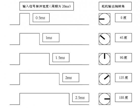
If the servo makes abnormal noise, there is usually a problem with the pulse frequency. The standard PWM period of the microservo is 20ms. When its high-level time is in the range of 0.5ms to 2.5ms, the corresponding angle is 0 to 180 degrees. The library defaults to this parameter setting, so there is no need for the user to calculate the relevant values by himself.
When the project requires multiple servos to work together, such as making a robotic arm or a multi-joint robot, using the library is particularly convenient. You just need to create multipleservoobjects, each bound to a different GPIO pin, and then set their angles individually. There is a little trick: when usingpwmio., putSet to 50, which is the standard frequency of the servo. If it is this kind of PWM expansion board, the code is almost the same. You only need to change the I2C address to control 16 servos at once, which is very suitable for complex projects.
Many friends reported that the servo suddenly stopped moving or the angle was not correct. The most common reason is a power supply problem. The instantaneous current of a microservo can reach more than 1A. If multiple servos are activated at the same time, an instantaneous voltage drop will cause the Raspberry Pi to restart. The solution is to use a separate regulated power supply to power the servo, and the ground wire should be connected to the ground of the Raspberry Pi. Another pitfall is the angle range. The mechanical limit of some models is only 0-120 degrees. If you force it to give it a 180-degree command, the gearbox will get stuck and make a "click" sound. At this time, power off immediately and check the specific parameters of the servo model.
By controlling the micro-servo servo, you are actually quickly transforming your creativity into a movable work. From single servo debugging to multi-channel linkage, it can help you save a lot of debugging time. Now that you have read this, you might as well ask yourself: In your next innovative product, what kind of action effects can these small servos help your design achieve that you never dared to think of before?
Update Time:2026-03-23
Contact Kpower's product specialist to recommend suitable motor or gearbox for your product.


