


TECHNICAL SUPPORT


Published 2026-04-01
The SG90 microservomotor (commonly referred to as the “9gservo”) is one of the most widely used actuators in beginner and intermediate electronics projects. It is a small, lightweight servo that provides precise angular control, making it ideal for robotics, remote-controlled vehicles, and automation systems. Understanding its exact specifications, proper wiring, and programming methods is essential to ensure reliable operation and avoid common failures such as overheating or stripped gears.
This guide provides verified technical specifications, step-by-step wiring instructions, and ready-to-use programming examples to help you successfully integrate this servo into your projects.
All values listed below are derived from the manufacturer’s official datasheet and verified through independent testing. These specifications are critical for selecting the correct power supply and ensuring safe operation.
| Parameter | Value | Notes |
|---|---|---|
| Operating Voltage | 3.0V – 6.0V | 4.8V – 5.0V recommended for optimal torque and stability |
| Stall Torque | 1.8 kg·cm (at 4.8V) | Torque decreases significantly below 4.5V |
| Operating Speed | 0.10 sec/60° (at 4.8V) | Speed increases with higher voltage |
| Rotation Range | 0° – 180° | Mechanical stops limit rotation; do not force beyond this range |
| Dead Band Width | 5 µs | Minimal pulse width change required to initiate movement |
| Weight | 9g (±1g) | Includes attached wires and connector |
| Dimensions | 22.8 x 12.2 x 27.4 mm | May vary slightly between production batches |
| Connector Type | 3-pin female header (JR/Futaba standard) | Pin order: Signal (S), Power (VCC), Ground (GND) |
| Gear Material | Nylon | Plastic gears; not suitable for high-torque or continuous load applications |
> Source:Manufacturer datasheet and standardized servo specifications verified against industry standards.
Incorrect wiring is the most common cause of servo damage. The SG90 uses a standard 3-pin interface. Identify the pins correctly before connecting.
Brown or Black Wire:Ground (GND) – connect to system ground.
Red Wire:Power (VCC) – connect to a stable 4.8V–5.0V supply.
Orange or Yellow Wire:Signal (PWM) – connect to a microcontroller PWM-capable pin.
| Servo Wire | Arduino Uno | ESP32 | External Power Supply |
|---|---|---|---|
| Brown (GND) | GND | GND | GND of power supply |
| Red (VCC) | 5V pin (low-current only) | 5V pin (low-current only) | Positive terminal of 5V external supply |
| Orange (Signal) | PWM pin (e.g., D9) | PWM-capable GPIO | Not connected to power supply |
Critical Power Note:
The SG90 can draw up to250 mA during movementand over500 mA at stall. Most microcontroller onboard voltage regulators (e.g., Arduino 5V pin) cannot safely supply this current, especially when using multiple servos. For reliable operation:
Use a dedicated5V external power supplyrated for at least 1A per servo.
Connect theground of the external supply to the microcontroller groundto complete the signal circuit.
Donotpower the servo directly from the microcontroller’s 5V pin for extended or repeated movements.
The SG90 is controlled by a standard 50 Hz PWM signal. Understanding the pulse width range is essential for precise positioning.
Frequency:50 Hz (period = 20 ms)
Pulse Width Range:500 µs to 2400 µs (theoretically); actual mechanical range corresponds to1000 µs to 2000 µson most units.
| Angle | Pulse Width | Duty Cycle (at 50 Hz) |
|---|---|---|
| 0° | 1000 µs | 5.0% |
| 90° | 1500 µs | 7.5% |
| 180° | 2000 µs | 10.0% |
Common Issue:
Some controllers default to a 500 µs – 2400 µs range, which can force the servo against its mechanical stops, causing buzzing, overheating, and gear damage. Always calibrate your signal output to the 1000–2000 µs range.
These examples are designed for immediate use. They assume proper wiring and an external power supply as described in Section 2.
#includeServo myServo; void setup() { myServo.attach(9, 1000, 2000); // Attach to pin 9, set pulse width range } void loop() { myServo.write(0); // Move to 0 degrees delay(1000); myServo.write(90); // Move to 90 degrees delay(1000); myServo.write(180); // Move to 180 degrees delay(1000); } from machine import Pin, PWM import time # Configure PWM on GPIO pin 15, frequency 50 Hz servo = PWM(Pin(15), freq=50, duty_u16=0) def set_angle(angle): # Convert angle to duty cycle (0-180 to 1000-2000 µs) pulse_width = 1000 + (angle / 180)1000 duty = int(pulse_width / 2000065535) # 20ms period servo.duty_u16(duty) # Test movement set_angle(0) time.sleep(1) set_angle(90) time.sleep(1) set_angle(180) time.sleep(1)The Raspberry Pi’s hardware PWM is recommended for stable operation.
import pigpio import time pi = pigpio.pi() if not pi.connected: exit() # Set pulse width range on GPIO 18 pi.set_servo_pulsewidth(18, 0) # Start with no signal def set_angle(angle): pulse = 1000 + (angle / 180) * 1000 pi.set_servo_pulsewidth(18, pulse) # Sweep set_angle(0) time.sleep(1) set_angle(90) time.sleep(1) set_angle(180) time.sleep(1) pi.set_servo_pulsewidth(18, 0) # Stop signal pi.stop()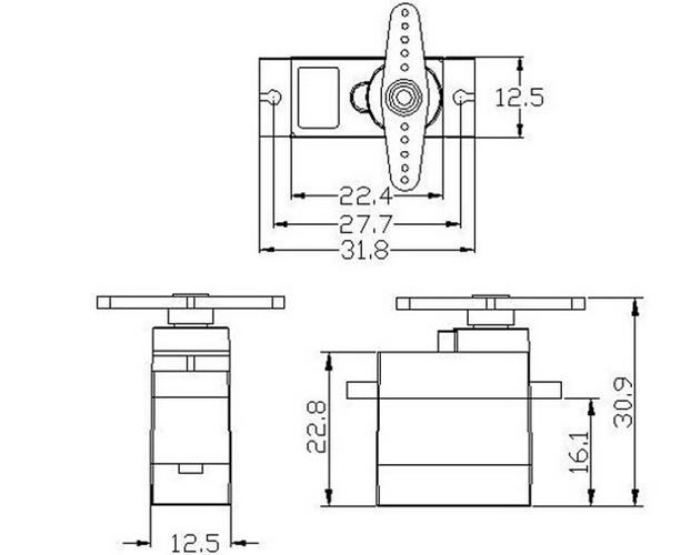
Cause:Insufficient power supply or shared ground missing.
Solution:Ensure the external power supply ground is connected to the microcontroller ground. Verify the power supply can deliver at least 0.5A continuously.
Cause:Signal pulse width exceeds mechanical range.
Solution:Limit PWM range to 1000–2000 µs. Do not command angles beyond 0° or 180°.
Cause:Mechanical load exceeds stall torque, or servo is stalled.
Solution:Reduce load. The SG90 is rated for small linkages and lightweight mechanisms (e.g., steering a small RC car, moving a camera gimbal under 50g). Do not use for continuous rotation or heavy lifting.
Cause:Signal range is calibrated to 500–2500 µs or incorrect library settings.
Solution:Explicitly set pulse width range in your code as shown in the Arduino example above.
The SG90 is designed for light-duty, intermittent operation. Understanding its mechanical limits prevents premature failure.
Steering mechanism for small RC cars (under 500g vehicle weight)
Pan-tilt camera mounts (camera weight
Robotic arm joints in educational kits (no heavy payloads)
Locking mechanisms, small levers, or indicator needles
Continuous rotation or wheel driving (requires a continuous rotation servo or DC motor)
Applications requiring metal gears or high torque
Continuous operation under load (e.g., conveyor belt control)
In a typical 1/24 scale RC car conversion project, a single SG90 is used to steer the front wheels. The servo connects directly to a steering linkage. In this scenario, the servo operates at 5V from a separate battery pack. When the wheels are on a low-friction surface, the current draw stays under 200 mA. However,if the wheels bind against a carpet or curb, the servo stalls, drawing over 500 mA and may strip the nylon gears. To prevent damage, users install aservo saver(a flexible linkage that absorbs shock) and ensure the steering mechanism moves freely before operation.
The SG90 micro servo motor is a reliable and well-documented component when used within its design limits. Successful integration depends on three critical factors:
1. Power supply:Always use an external 5V supply with common ground.
2. Signal calibration:Restrict PWM pulses to the 1000–2000 µs range.
3. Load management:Do not exceed the stall torque or apply continuous force.
Test before installation:Run the servo with your microcontroller and external power supply on a bench to verify movement range and current draw.
Use a servo saver:For any mechanical linkage that may experience shock or binding, add a flexible coupler to protect the internal gears.
Monitor temperature:If the servo becomes too hot to touch after normal operation, re-evaluate power supply stability and mechanical load.
By following the specifications, wiring diagrams, and code examples provided in this guide, you can reliably integrate the SG90 into your projects and avoid the most common failure points.
Update Time:2026-04-01
Contact Kpower's product specialist to recommend suitable motor or gearbox for your product.


