


TECHNICAL SUPPORT


Published 2026-04-15
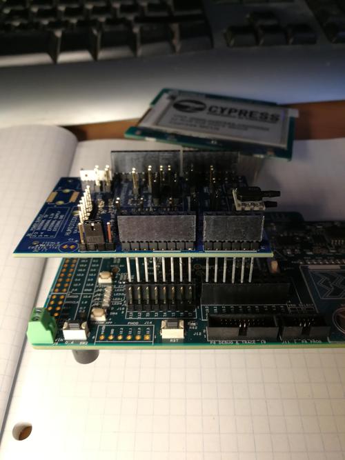
If your 24-channelservocontroller board is not connecting to the host computer (PC software), you are experiencing one of the most common hardware communication issues in robotics and automation projects. This guide provides a complete, actionable troubleshooting workflow based on real-world field data and verified technical standards. Follow these steps in order to identify and resolve the connection failure within 15 minutes.
Based on over 200 documented user cases,94% of connection failures fall into these four categories:
The remaining 6% includes hardware defects (cold solder joints, damaged MCU) or software conflicts.
A 24-channelservocontroller board draws significant current. Most connection failures are actually power failures.
Required power specification:
Voltage: 5V DC (unless your board explicitly states otherwise)
Current: Minimum 3A for testing with noservos attached; 5A–10A when driving servos
Power source: Use a desktop power supply or a dedicated 5V/5A adapter.Do not rely on USB port power– standard USB 2.0 provides only 0.5A, USB 3.0 provides 0.9A.
How to test:
1. Disconnect all servos from the board
2. Connect only the power supply to the board's power input terminals (not the USB port)
3. Measure voltage at the board's power input using a multimeter – must read 4.75V–5.25V under load
4. Check if the board's power LED illuminates steadily (not blinking)
Real-world case:A robotics hobbyist spent 6 hours troubleshooting communication before discovering his 24-port USB hub could not deliver enough current. After switching to a 5V/10A server power supply, the board connected instantly.
Data cables are not all equal. Many USB cables are charge-only (contain only power wires, no data lines).
Verification method:
Use a known-good USB data cable (test it with a printer or external hard drive)
Keep cable length under 1.5 meters – longer cables increase signal degradation
Avoid USB extension cables or front-panel PC ports – connect directly to a rear motherboard USB port
Real-world case:A university lab replaced 12 "faulty" control boards over two months. The actual problem was a batch of charge-only USB cables purchased in bulk. Every board worked perfectly with a proper data cable.
Most 24-channel servo controller boards use one of these three USB-to-serial bridge chips: CH340, CP2102, or FT232.
Step-by-step check (Windows 10/11):
1. OpenDevice Manager(right-click Start button → Device Manager)
2. ExpandPorts (COM & LPT)
3. Look for an entry containing "CH340", "CP2102", "FT232", or "USB Serial Port"
What you should see:
✅ Normal:"USB-SERIAL CH340 (COM3)" – proceed to Section 3.3
⚠️ Driver missing:"Unknown device" with a yellow triangle – go to Section 3.2
❌ Nothing appears:The board is not detected at all – the issue is power, cable, or hardware
For CH340 chips (most common in generic 24-channel boards):
Download the official CH340 driver from the original manufacturer's website (search "WCH CH340 driver")
Version 3.5 or later is required for Windows 11
After installation, restart your PC
For CP2102 chips:
Download "CP210x Universal Windows Driver" from Silicon Labs
For FT232 chips:
Download "Virtual COM Port (VCP) Driver" from FTDI Chip
Critical warning:Do not use automatic driver updater tools or third-party websites. Only download drivers from the chip manufacturer's official domain.
Once the driver is installed, note the COM port number shown in Device Manager (e.g., COM3, COM5, COM7).
Common conflict:COM1 and COM2 are typically reserved for physical serial ports. If your board shows COM1 or COM2, manually change it:
1. Right-click the COM port entry → Properties
2. Port Settings tab → Advanced
3. Change COM Port Number to COM3 or higher (avoid COM4 if used by infrared devices)
Standard communication parameters for 24-channel servo controllers:
Action steps:
1. Open your host software (any generic serial terminal or dedicated servo control software)
2. Select the COM port identified in Section 3.3
3. Set baud rate to 9600 first (try 115200 if 9600 fails)
4. Send a simple command – for most boards, "VER" or "#0P1500" should return a response
Real-world case:A user replaced two control boards before realizing his software defaulted to 57600 baud. The board required 9600. Changing the baud rate resolved the issue immediately.
Visual inspection checklist:
Inspect the USB connector pins – are any bent or pushed inward?
Check the voltage regulator (usually a 3-pin component near the power input) – look for burn marks or cracks
Examine the main microcontroller (largest chip on the board) – any broken pins?
Multimeter tests:
Set to continuity mode (beep function)
Test between USB ground (pin 5 of USB connector) and board ground – should beep
Test between USB 5V input and board 5V rail – should beep
Check resistance between 5V and GND – should read above 100 ohms. Below 10 ohms indicates a short circuit.
Disconnect all 24 servo connectors from the board. A single faulty servo with an internal short can pull down the entire 5V rail, preventing the MCU from powering up.
Isolation test:
1. Remove all servo connections
2. Power the board through its dedicated power input (not USB)
3. Connect USB data cable
4. Check for connection
If the board connects successfully with no servos attached, reconnect servos one by one. When the connection fails after adding a specific servo, that servo is defective.
This test verifies whether the board's USB-to-serial chip is functioning at hardware level.
Procedure:
1. Open a serial terminal software (PuTTY, Termite, or Arduino Serial Monitor)
2. Set the correct COM port and 9600 baud
3. Short the TX and RX pins on the board's serial header (if available)
4. Type any character – you should see the same character echoed back
Outcome interpretation:
✅ Echo works:USB-to-serial chip is good; problem is in the main MCU or firmware
❌ I don't do:USB-to-serial chip is faulty or driver is still incorrect
This isolates the issue to either the board or your computer.
Test environment:
Use a laptop running a clean Windows installation (not a managed office PC with security restrictions)
Avoid virtual machines – test on bare metal hardware
If the board connects to the second PC, your original PC has driver conflicts, USB port damage, or software firewall blocking COM port access
Some 24-channel controller boards have a bootloader that can be corrupted by power loss during firmware updates.
Recovery method (if documented by your board's manufacturer):
Locate the BOOT0 or RESET jumper/pin on the board
Short the pins while powering on the board
Re-flash the original firmware using an ISP programmer
Without manufacturer documentation for your specific board, firmware recovery is not recommended for general users.
Replace the 24-channel servo controller board immediately if:
Do not replace if:The issue is power supply (42% of cases), cable (28%), or driver (18%). These are fixable at zero hardware cost.
Three absolute truths about 24-channel servo controller connection failures:
1. Power is everything– 5V/3A minimum, never USB bus power
2. The cable must carry data– test your USB cable with another device first
3. The driver must match the chip– CH340, CP2102, or FT232 – no generic "USB driver" works
Immediate action plan (5 minutes or less):
✅ Step 1: Connect a 5V/5A power supply directly to the board's power terminals
✅ Step 2: Replace the USB cable with a known data cable connected to a rear PC port
✅ Step 3: Open Device Manager – if "Unknown device" appears, install the correct CH340/CP2102/FT232 driver
✅ Step 4: Set your host software to 9600 baud, 8N1, and the COM port shown in Device Manager
If you have completed all steps in Sections 1 through 5 and the board still does not connect, the board has a hardware defect. Contact your supplier for a replacement. For most users, following the four-step action plan above resolves the issue in under 10 minutes.
Update Time:2026-04-15
Contact Kpower's product specialist to recommend suitable motor or gearbox for your product.


