



























TECHNICAL SUPPORT


Published 2026-07-10
Quick Answer
To power aservomotor, you must connect the power wire (typically red) to a DC power supply within the specified voltage range, the ground wire (brown or black) to the power supply ground, and the signal wire (white, yellow, or orange) to a PWM-capable controller such as an Arduino or PLC. The power supply must deliver sufficient current for both theservoand the controller, and the voltage must match theservo's rated range—typically 4.8V to 7.2V for standard hobby servos and 24V to 48V for industrial servo drives. Incorrect wiring or underpowering is the most common cause of servo jitter, overheating, or failure.
How to Power a Servo Motor: Wiring, Voltage, and Setup Guide
When a production line stops unexpectedly or a robotic arm fails to hold position, the root cause is often not the servo motor itself but how it is powered. Engineers and procurement managers spend time comparing torque curves and accuracy specifications, yet the most frequent problem in motion control systems is improper power delivery.
A servo motor, whether a smallmicro servoused in a pick-and-place unit or a large industrial servo drive in a CNC machine, requires a stable DC power source that matches its voltage and current demands. The wiring diagram may look simple—three wires—but the practical requirements behind those connections can determine whether your system runs smoothly for years or fails within weeks.
Before you select a servo or design the control cabinet, understanding how to power the motor correctly will save cost, reduce downtime, and prevent unnecessary hardware damage. This guide walks through the standard wiring method, power supply selection criteria, and common mistakes that buyers and engineers should avoid.
Table of Contents
The Three Wires: What Each Does and Why It Matters
Voltage Requirements: Matching the Power Supply to the Servo
Current and Inrush: Why a Small Power Supply Causes Big Problems
Wiring Sequence: Step-by-Step Connection Method
Power Supply Types: When to Use a Battery, a Wall Adapter, or an Industrial Supply
Grounding and Noise: Preventing Interference in Sensitive Applications
Common Wiring Mistakes That Damage Servos
Quick Connection Reference Table
Questions Buyers Often Ask About Servo Power
Selecting the Right Servo and Power Setup for Your Application
The Three Wires: What Each Does and Why It Matters
Every standard servo motor, from hobby-grade units to many industrial models, uses three wires. The color code may vary slightly between manufacturers, but the function is universal.
The power wire, usually red, connects to the positive terminal of your DC power supply. The ground wire, typically brown or black, connects to the negative terminal. The signal wire, often white, yellow, or orange, carries the pulse-width modulation (PWM) signal from your controller.
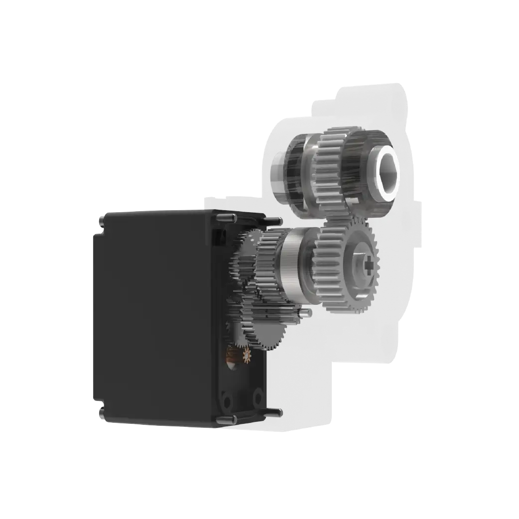
The most common wiring mistake is connecting the power wire to the controller's 5V output instead of a separate power supply. A controller's onboard regulator can only deliver a few hundred milliamps. When a servo draws one or two amps during normal operation, the controller either shuts down, resets, or damages its voltage regulator. This is why dedicated servo power is not optional—it is essential for reliability.
Voltage Requirements: Matching the Power Supply to the Servo
Servo motors are designed to operate within a specific voltage range. Exceeding the maximum voltage can burn the internal electronics. Running below the minimum voltage causes weak torque, slow response, and erratic positioning.
Standard hobby and light industrial servos typically operate between 4.8V and 7.2V. For a 4.8V system, the servo delivers lower speed and torque. At 6.0V or 7.2V, performance increases noticeably. However, not all servos are rated for 7.2V. Always check the datasheet.
Industrial servo drivesoften require 24V DC for the control logic and a separate 24V to 48V DC or 200V to 480V AC for the motor power stage. In these systems, wiring the control power incorrectly can prevent the drive from booting up or cause fault codes.
For buyers comparing different types of servos, the voltage requirement directly affects thepower supply selectionand the overall system cost. A servo that requires 48V needs a more expensive power supply and higher-rated cables than a 24V unit.
Current and Inrush: Why a Small Power Supply Causes Big Problems
The rated current printed on a servo is usually the continuous running current. But what matters more in practice is the stall current and inrush current.
When a servo starts moving from a stop, or when it holds a heavy load against gravity, the current draw can spike to two or three times the continuous rating. If your power supply cannot deliver this peak current, the voltage drops, the servo loses torque, and the controller may interpret the voltage drop as a signal error.
A general rule is to select a power supply rated for at least 1.5 times the total continuous current of all servos in the system. For a single servo drawing 2A continuously, use a 3A or higher power supply. For a multi-axis system, calculate the sum of all continuous currents and multiply by 1.5. Then add a safety margin of 20%.
Wiring Sequence: Step-by-Step Connection Method
1. Turn off all power before connecting wires.
2. Connect the ground wire (brown/black) to the negative terminal of the DC power supply.
3. Connect the power wire (red) to the positive terminal of the DC power supply.
4. Connect the signal wire (white/yellow/orange) to the PWM output pin on your controller.
5. Connect the controller's ground pin to the same power supply ground. This common ground is critical for signal integrity.
6. Turn on the power supply first, then power the controller.
7. Send a neutral PWM signal (typically 1.5ms pulse) before commanding movement.
If the servo jitters, hums, or does not respond, check the ground connection first. A floating ground is the most frequent cause of erratic servo behavior.
Power Supply Types: When to Use a Battery, a Wall Adapter, or an Industrial Supply

Battery poweris suitable for mobile robots and portable equipment. Lithium-polymer or lithium-ion batteries can deliver high current bursts, but voltage drops as the battery discharges. You must account for the minimum operating voltage of the servo when the battery is near empty.
Wall adaptersare convenient for benchtop testing and low-power applications. However, many adapters have poor voltage regulation and may not deliver the rated current continuously. Always test under load.
Industrial switched-mode power supplies (SMPS)are the most reliable choice for production environments. They provide stable voltage, short-circuit protection, and sufficient current reserves. For multi-axis systems, a 24V or 48V industrial SMPS with a power factor correction (PFC) rating is recommended.
Grounding and Noise: Preventing Interference in Sensitive Applications
In a motion control system, the servo motor is both a power device and a source of electrical noise. If the power ground and signal ground are not properly separated, the noise from the motor current can couple into the PWM signal, causing position errors.
The best practice is to use a star ground topology. All ground wires—power supply, controller, servo—should meet at a single point. Avoid daisy-chaining ground wires from one device to the next.
For high-precision applications, such asCNC machiningorrobotic assembly, consider using a shielded signal cable. Connect the shield at one end only to prevent ground loops.
Common Wiring Mistakes That Damage Servos
Connecting the servo power wire to the controller's 5V pin instead of a dedicated power supply.
Using a power supply with correct voltage but insufficient current capacity.
Reversing the power and ground wires—this can destroy the servo electronics instantly.
Operating the servo at a voltage higher than its maximum rating, even briefly.
Running long power cables with insufficient wire gauge, causing voltage drop under load.
Driving the servo signal line with a 5V logic controller when the servo expects 3.3V logic, or vice versa.
Powering the controller and the servo from separate, unconnected power supplies without a common ground.
Quick Connection Reference Table
Questions Buyers Often Ask About Servo Power
Q: Can I power a servo directly from an Arduino pin?
No. An Arduino pin can only supply about 40mA. A servo needs 500mA to several amps. Always use an external power supply.
Q: What happens if I use a power supply with lower voltage than rated?
The servo will have reduced torque, slower speed, and may not hold position under load. In extreme cases, it may not move at all.
Q: Can I use a 12V power supply for a 6V servo?
No. 12V will exceed the servo's maximum voltage and likely damage the internal electronics. Use a voltage regulator or a step-down converter.
Q: Do I need a separate power supply for each servo?
Not necessarily. One power supply can drive multiple servos if the total current capacity is sufficient. Use a terminal block for distribution.
Q: Why does my servo twitch when powered but not connected to a controller?
The signal wire is floating. A floating input can pick up noise. Either connect the signal wire or pull it to ground with a resistor.
Q: How long can servo power cables be before voltage drop becomes a problem?
For 18 AWG wire at 2A, keep cable length under 5 meters. For longer runs, use thicker wire (16 AWG or 14 AWG) and verify voltage at the servo end.
Q: Is there a difference between powering a servo and powering a servo drive?
Yes. A servo drive requires both control power (typically 24V DC) and main power (24V-480V AC or DC). Wiring them separately is critical.
Q: What is the most reliable way to test if my servo power is correct?
Measure voltage at the servo connector under load. If voltage drops more than 5% from the no-load value, the power supply or wiring is insufficient.
Selecting the Right Servo and Power Setup for Your Application
Choosing a servo is not just about torque and speed. The power supply, wiring method, and grounding scheme are equally important to system reliability. A servo with excellent specifications will perform poorly if its power source is undersized or its ground is floating.
Before finalizing yourservo motor selection, confirm the voltage and current requirements with the supplier. Ask for the stall current and inrush current, not just the continuous rating. Verify that your power supply can deliver peak current without sagging.
If you are replacing an existing servo or designing a new motion control system, check the wiring diagram against your power infrastructure. A single overlooked ground connection can cause hours of troubleshooting.
For buyers evaluating multiple suppliers, request documentation on recommended power supply specifications and wiring guidelines. A supplier that provides clear power requirements is more likely to deliver reliable hardware and support.
When you are ready to move forward, send your system specifications to the supplier and ask for a power supply recommendation tailored to your application. A quick engineering review at the design stage prevents costly field failures later.
Update Time:2026-07-10

Contact Kpower's product specialist to recommend suitable motor or gearbox for your product.


