


TECHNICAL SUPPORT


Published 2026-02-28
The biggest headache when playing withservos is the wiring problem, especially for high-torqueservos like this. If the wiring is wrongly connected, it may not turn at all, or it may be burned directly. Many novices get this big thing for the first time and are often confused when looking at the three wires and don't know how to start. Today we will thoroughly explain this matter so that you can get started directly after reading it.
The colors of the three wires extending out of the servo are usually relatively fixed. The red wire in the middle, no need to think about it, must be the positive terminal of the power supply, responsible for providing power to the servo. The brown or black wire is the negative pole, also called the ground wire, and needs to be connected to the negative pole of the power supply. The remaining orange, yellow or white line is the signal line, which is responsible for receiving instructions from the control board and telling the servo to which angle to turn. Remember these three colors, and wiring is half the battle.
Many friends can't tell the difference between positive and negative poles. In fact, there is a simple way to distinguish them. If you look carefully at the connector of the servo cable, there is usually a small chamfer or bulge on it. This fool-proof design is to prevent you from plugging it in backwards. If you really can’t tell, remember that the red wire of most servos is in the middle, with signal and ground wires on both sides. This rule is very general.
This thing is an electric tiger. When working, the current can reach 1A or even higher. When the rotor is blocked, the current is even more terrifying. You must not expect to draw power directly from the 5V pin of the Raspberry Pi or Raspberry Pi, as this will most likely burn out your motherboard. You have to prepare a separate power supply for it, such as a 7.2V battery pack or a high-current voltage stabilizing module that can output 5-6V.
Pay special attention when wiring. The negative pole of the servo power supply must be connected to the GND of the control board. This is called a common ground. If it is not connected, the signal will be messed up, and the servo will shake or not obey the command. You can connect the negative terminal of the power supply to the GND of the control board with a Dupont wire, so that the signal transmission is stable.
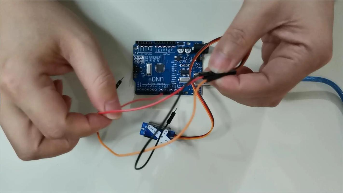
The signal line should be connected to the pin of the control board that supports PWM output. For UNO, it is the digital pins marked with the "~" symbol. If it is a Raspberry Pi, although it does not have hardware PWM, it can be simulated through software or use such a specialized servo driver board to output signals, and the effect will be much better.
The connection method is very simple, just like inserting building blocks. But be careful, never plug the signal line into the power supply or GND. If you are using a servo driver board, it will be easier. Just plug the servo directly into the channel of the driver board, and then connect the driver board and the control board. The driver board can also help solve the power supply problem.
The most common mistake is insufficient power. You write the program with great expectations, but the servo only shakes slightly and then stops moving. Nine times out of ten, the power supply is not keeping up. Also, the signal line is connected to an ordinary digital pin instead of a PWM pin. In this way, the servo will only stay in one position and cannot accurately control the angle.
In addition, be sure to turn off the power before wiring. If you accidentally short-circuit during live operation, sparks will fly, and the control circuit board in the servo will be scrapped in an instant. Develop a good habit of checking the wiring after connecting it to make sure there is no problem before turning on the power. This can save a lot of wasted money.
After connecting the wires, test it with a simple program. For example, let the servo slowly turn from 0 degrees to 180 degrees, and then back again. If the servo can move smoothly without abnormal jitter or noise, congratulations, the wiring is successful. If it doesn't work, quickly cut off the power and check to see if the common ground is not done properly or the power supply voltage is not enough.
️ A little tip: When the power is off, gently turn the output disk of the servo by hand. It should not turn because the reduction gear is stuck. If it can turn easily, the internal gear of the servo may be damaged. After powering on, the servo should be able to stop steadily at the designated position. You should feel a lot of resistance when you pull it off with your hands. This is considered normal.
The torque is large and the metal gear is durable. It is especially suitable for use in robot joints, such as making a six-legged robot or a robotic arm. It is also perfectly sufficient to use it to provide steering power for remote control model cars and boats. You can even DIY a gimbal and fix the camera on the servo to realize automatic face tracking.
In fact, the gameplay of the servo is much more than just turning around. By combining various sensors, such as ultrasonic and infrared, it can sense the environment and respond. You can use it to make a trash can that opens and closes automatically, or a solar panel bracket that rotates according to the angle of light. As long as the foundation of wiring is laid, the rest depends entirely on your imagination.
Seeing this, you should have an idea about the wiring. When you connected the servo for the first time, did you have any troubles due to wrong wiring sequence or insufficient power supply? Welcome to share your experience in the comment area. Let’s communicate and avoid pitfalls together. If you find it useful, don’t forget to give it a like and share it with more friends!
Update Time:2026-02-28
Contact Kpower's product specialist to recommend suitable motor or gearbox for your product.


