


TECHNICAL SUPPORT


Published 2026-03-12
I have been working on steering gear control for a while, and I have gone through more pitfalls than I have eaten. At first I thought it would turn when I connected it to a PWM signal, but the result was that it either vibrated like Parkinson's or couldn't turn to the angle I wanted. Later, I calmed down and did several rounds of experiments, and then I found some clues. Today I will share with you some practical insights to help you avoid detours.
When you first come into contact withservos, you will definitely be confused by those terms. Don't worry, let's take it apart and take a look. The steering gear is essentially a "small closed-loop system" that integrates a DC motor, reduction gear, and control panel. You give it a pulse signal, and it detects the current angle through the internal potentiometer and compares it with its memorized target position. If it is not correct, it will rotate until it is aligned.
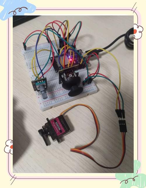
What I did at that time was very stupid but very effective: I took a cheap 9gservoand took it apart and looked at it. Seeing the potentiometer rotate with the output shaft with my own eyes, I instantly understood what the feedback was. Then I used an oscilloscope to look at the control signal and found that the high-level time was from 0.5ms to 2.5ms, corresponding to 0 degrees to 180 degrees. The logic became clear at once.
The program looks simple, just send a PWM, but it is not easy to achieve stability. At first, I used software delay to simulate PWM. As a result, the servo rotated one after another. Because the microcontroller had to do other work, the delay was interrupted. Later, it was replaced by a timer interrupt, and a hardware timer was specially set aside to generate PWM waves, and the servo immediately became smooth.
There is another detail that you may overlook: the status of the GPIO port at the moment of power-on. If the pin output of the microcontroller is uncertain when it is started, the servo will jerk violently, which can cause a shock at least, or damage the mechanical structure at worst. My solution is: first pull all the servo-related pins low when powering on, and then slowly bring them to the target angle after initialization is completed. This trick is particularly effective.
Speaking of jitter, there are a lot of tricks here. The most common problem is the power supply. The current when the servo is started can soar to 1A or even higher. If the power supply cannot handle it and the voltage drops, the microcontroller on the control board will have to be restarted. I used a mobile phone power bank to power a single servo, and it was very stable.
Another thing that is easily overlooked is interference on the signal line. Especially when the servo cable is relatively long, the PWM signal acts like an antenna and is prone to coupling noise. The solution is also simple: use a twisted pair for the signal line, or directly pull it down to ground with a 1k resistor, which can effectively suppress jitter. Also, if your PWM frequency is too far from the 50Hz (period 20ms) required by the servo, it will also lead to inaccurate control.
There are all kinds of servos on the market, and if you choose the wrong project, your work will be in vain. First look at the torque, which is directly related to whether it can drive your load. I usually calculate the torque required for the load and leave a 30% margin. For example, if you want to make a robotic arm, the most distal joint requires the smallest torque, so the base must be several times larger.
Then look at the speed, using the sec/60° indicator. For example, 0.12sec/60° is faster than 0.18. But be aware that torque and speed are often contradictory, and those with greater torque are usually slower. The last thing is the working voltage and size. You have to see whether your board can afford it and whether the structural parts can be installed. The durability of metal gears and the cheapness of plastic gears depend on your budget and application scenarios.
If you want to make a robot, you must control several servos at the same time. There are only a dozen IO ports in one block. Direct control is theoretically possible, but in practice it cannot be handled, and the starting current is too high at the same time. My approach is to use a servo control board, such as this I2C interface board, which can manage 16 channels. The main control only sends commands, and all PWM is generated by it.
You should also pay attention to the software. Never let all the servos jump from 0 degrees to 180 degrees at the same time. The current can knock out your power supply. I made a "staggered start" in the code, only moving one servo step every 20ms, or using a slow start method to let them slowly "climb" to the target position, so that the current is much gentler.
The worst lesson I learned was that the power supply was connected in reverse. Only when there was smoke did I realize that ordinary servos do not have reverse connection protection. Later I learned to string diodes on the power cord or work on the plug. Fool-proof design is very important. There is also a mechanical limit. The angle must be limited in the program, otherwise the servo will hit the wall and the gear will soon collapse.
In addition, when debugging, don't just stare at the code, pay more attention to the mechanical assembly. One time, the servo was shaking all the time, and after struggling with the program for three days, I finally found that the connecting rod screw was loose and the gap was too large. Since then, I have developed a habit: first check the machinery, then check the circuit, and finally move the code. This sequence has saved me a lot of time.
What's the weirdest problem you've ever encountered with servo control? Let’s chat in the comment area and let’s study together. If you find it useful, give it a like and share it with more friends, so that everyone can work on the project smoothly!
Update Time:2026-03-12
Contact Kpower's product specialist to recommend suitable motor or gearbox for your product.


