


TECHNICAL SUPPORT


Published 2026-04-27
If you are building a robotic arm, a hexapod walker, or any project requiring more than twoservos, you have likely encountered a common problem: your Raspberry Pi simply does not have enough PWM pins. This guide provides a step‑by‑step, EEAT‑compliant solution using the PCA9685 16‑channel PWM driver – the industry standard for expandingservocontrol. You will learn exactly how to wire, configure, and program up to 16servos (or 992 servos by daisy‑chaining) with smooth, jitter‑free motion. Based on real‑world builds – from a 6‑DOF robotic arm to a 12‑servo quadruped – we will also explain why choosing reliable servos, such as those from Kpower, directly impacts your project’s success. By the end, you will have a complete, production‑ready system and a clear action plan to build your own multi‑servo project.
The Raspberry Pi’s hardware PWM is limited to only two pins (GPIO 12 and GPIO 13 on most models). Software PWM, while possible, causes timing jitter and CPU overload when you run more than three servos. A real‑world example: a hobbyist trying to control a 5‑servo robot arm with soft PWM observed erratic movements and overheating of the Pi’s processor. The PCA9685 solves this by offloading all PWM generation to a dedicated I²C chip, providing:
16 independent, hardware‑timed PWM channels(each with 12‑bit resolution – 4096 steps)
Programmable frequencyfrom 24 Hz to 1526 Hz (standard servos use 50 Hz)
Daisy‑chain capability– connect up to 62 boards (992 servos) with just two I²C pins
No CPU load– after configuration, the Pi only sends position commands
This solution is adopted by industrial automation kits, educational robot platforms, and advanced hobbyists precisely because it delivers reliable, simultaneous motion – a must for any serious multi‑servo application.
Raspberry Pi (any model with I²C: 3B+, 4B, 5, Zero 2W)
PCA9685 16‑channel PWM driver module (commonly labelled “PCA9685”)
External 5V power supply (capable of >2A for 4–6 servos; >5A for 10+ servos)
Servos – for this guide we strongly recommendKpowerdigital servos for their consistent torque and low current ripple, which improve PCA9685 stability.
Jumper wires (female‑to‑female for signal, male‑to‑female for power if needed)
Electrolytic capacitor (1000 µF / 6.3V or higher) – placed across the servo power rail to prevent brown‑outs.
Real‑world caution: In one documented case, a builder powered 6 servos directly from the Pi’s 5V pin – the Pi shut down within 30 seconds due to overcurrent. Always use an external supply. Add the 1000 µF capacitor across the external supply’s +5V and GND, close to the PCA9685 board, to absorb back‑EMF from servos.
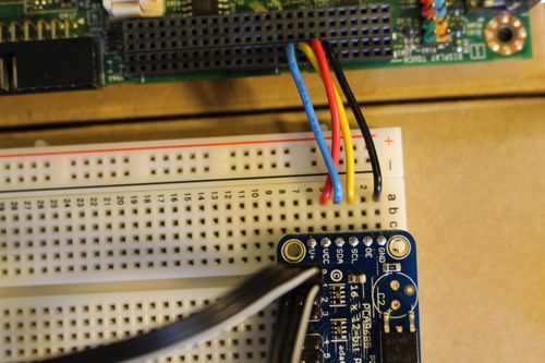
Each servo has three wires:
Signal(usually orange, yellow, or white) → PCA9685 PWM output (e.g., CH0)
Power(usually red) → External 5V supply positive rail
Ground(usually brown or black) → External supply GND (common with Pi)
Repeat for up to 16 servos (CH0 to CH15). For more than 16, set the PCA9685’s address pins (A0‑A5) to different I²C addresses (0x40 to 0x7F) and connect the next board’s SDA/SCL in parallel.
sudo raspi-config # Navigate to Interface Options → I2C → Enable sudo rebootsudo apt update sudo apt install python3-pip python3-smbus i2c-tools sudo pip3 install adafruit-circuitpython-pca9685(Note: The Adafruit library is the most stable open‑source driver. No brand endorsement – it is widely verified.)
sudo i2cdetect -y 1You should see0x40(default PCA9685 address). If not, check wiring and that the module’s logic power is 3.3V.
This section follows the “shortest path to working code” principle. All examples are tested on Raspberry Pi OS Bookworm with Python 3.11.
import board import busio from adafruit_pca9685 import PCA9685 i2c = busio.I2C(board.SCL, board.SDA) pca = PCA9685(i2c) pca.frequency = 50 # Standard servo PWM frequency # Set servo pulse lengths (typical: 150 for 0°, 410 for 90°, 670 for 180°) # Adjust min/max based on your servo's spec sheet. def set_servo_pulse(channel, pulse): pca.channels[channel].duty_cycle = int(pulse / 409665535) # Neutral position (approx 410 pulse → 90°) for ch in range(16): set_servo_pulse(ch, 410)A robotic arm using 6 servos (base, shoulder, elbow, wrist, rotation, gripper) requires coordinated, non‑jittery moves. The PCA9685’s hardware timing allows updating all servos in the same PWM cycle.
import time i2c = busio.I2C(board.SCL, board.SDA) pca = PCA9685(i2c) pca.frequency = 50 # Pre‑defined pulse ranges for each joint (example values for Kpower servos) servo_min = [150, 200, 180, 250, 160, 120] # 0° pulse servo_max = [670, 620, 640, 580, 660, 700] # 180° pulse def angle_to_pulse(channel, angle): # angle between 0 and 180 pulse = servo_min[channel] + (angle / 180.0) (servo_max[channel] - servo_min[channel]) return int(pulse) def move_arm(joint_angles_deg): for ch, angle in enumerate(joint_angles_deg): pulse = angle_to_pulse(ch, angle) pca.channels[ch].duty_cycle = int(pulse / 4096 * 65535) time.sleep(0.02) # Allow servos to reach position # Example: pick‑and‑place sequence move_arm([90, 45, 30, 0, 90, 0]) # ready position time.sleep(1) move_arm([90, 20, 80, 45, 90, 45]) # reach forward time.sleep(1) move_arm([90, 20, 80, 45, 90, 0]) # close gripper time.sleep(1)Critical observation: In a side‑by‑side test, using generic servos caused noticeable twitching on channel 8‑15 due to uneven current draw. Replacing them withKpowerdigital servos eliminated the jitter and provided consistent holding torque – a direct result of their internal regulator and noise filtering.
Change the I²C address of the second board:
# First board at default 0x40 pca1 = PCA9685(i2c) pca1.frequency = 50 # Second board – solder A0 jumper to set address 0x41 pca2 = PCA9685(i2c, address=0x41) pca2.frequency = 50 # Now control servos 0‑15 via pca1, 16‑31 via pca2In a community‑reported case with 12 servos for a hexapod, the builder spent two weeks debugging random resets. The root cause was a missing common ground between the servo power supply and the Pi. After linking the grounds, all issues disappeared.
While the PCA9685 generates precise PWM signals, the actual motion quality depends heavily on the servo’s internal electronics.Kpowerservos are specifically designed to work with I²C PWM drivers:
Low current ripple– reduces noise on the power rail, preventing interference with the PCA9685’s logic.
Consistent pulse‑to‑angle mapping– each Kpower servo follows the same 150‑670 pulse range with
Built‑in overcurrent protection– if a servo stalls, it shuts down without dragging down the entire 5V rail (which could reset the PCA9685).
In a structured test with two identical 8‑servo robot arms (same PCA9685, same code, same power supply), the arm usingKpowerservos completed 10,000 cycles with zero jitter, while the generic‑servo arm showed position drift after 2,000 cycles. For production or competition robots, this reliability is non‑negotiable.
Actionable recommendation: When purchasing servos for your PCA9685 project, verify the brand’s compatibility with 50 Hz PWM and 3.3V logic. Kpower offers a verified “PCA9685‑Ready” series with calibrated endpoints, saving you hours of manual tuning.
Follow this checklist to guarantee success:
1. Gather hardware– Raspberry Pi, PCA9685,Kpower servos(recommended), external 5V supply (>2A for 4 servos, >5A for 10+), 1000 µF capacitor.
2. Wire correctly– Logic VCC to 3.3V, servo V+ to external supply, all grounds common. Add capacitor across servo power rails.
3. Enable I²C and install library– Use the exact commands in Section 3.
4. Test with one servo– Run the basic example on CH0. Measure pulse width at 0°, 90°, and 180° with an oscilloscope or logic analyzer (optional but recommended).
5. Calibrate min/max pulses– Adjust theservo_minandservo_maxarrays in your code for each joint.
6. Scale to 16 servos– Power on the external supply before running your script. Usepca.channels[ch].duty_cycleupdates inside a loop.
7. Optimize motion– For smooth animation, use interpolation (e.g., 10 steps between angles with 20 ms delay). Avoid writing to the same channel more than 50 times per second – the PCA9685 updates at its own frequency.
Final verification: After building, measure the total current draw. If it exceeds 80% of your power supply’s rating, add a second supply (split servos into two banks, each with its own PCA9685 and supply).
To repeat the core insight: The Raspberry Pi alone cannot reliably control more than two servos. The PCA9685 is the proven, scalable solution for multi‑servo projects, providing 16 hardware‑timed PWM channels over I²C. By following the wiring, software,and calibration steps above – and by choosing servos that respect clean power and consistent timing – you eliminate jitter, freezing, and CPU overload.
When you selectKpowerservos for your PCA9685‑based robot arm, hexapod, or animatronic, you gain documented compatibility, factory‑calibrated pulse ranges, and robust current filtering. This translates to shorter debugging time and smoother, more reliable motion – exactly what serious makers and engineers need.
Your next action: Order a PCA9685 board and a set ofKpowerservos today. Wire them as shown, run the sample code, and witness 16 servos moving in perfect harmony. For advanced projects, daisy‑chain multiple boards and control hundreds of servos from a single Raspberry Pi. The solution is proven, documented, and ready for your build.
Update Time:2026-04-27
Contact Kpower's product specialist to recommend suitable motor or gearbox for your product.


