


TECHNICAL SUPPORT


Published 2026-05-06
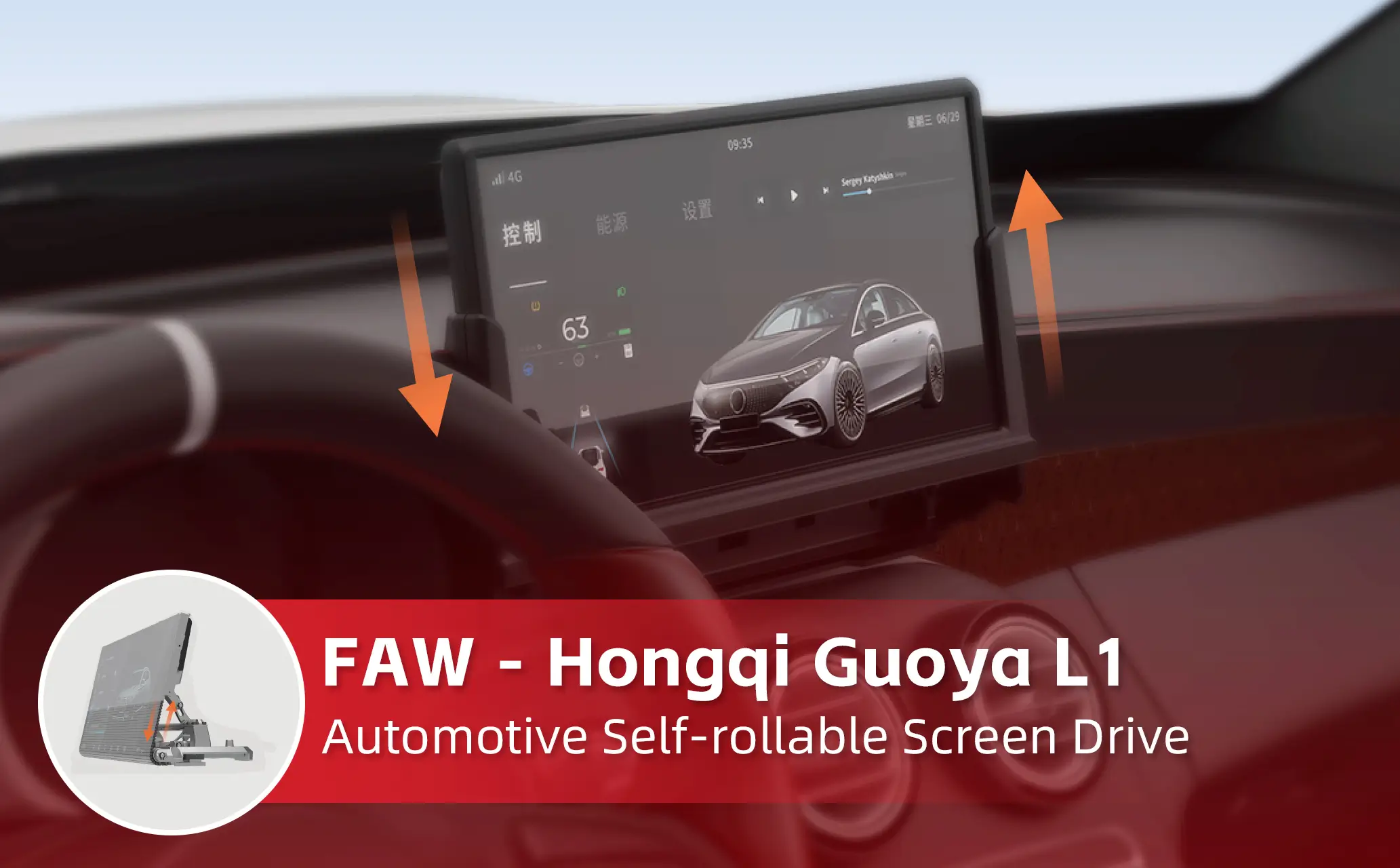
Want to find 3D drawings of the steering gear? Whether you use it to design robotic arms, participate in robot competitions, or serve for 3D printing verification, what you need is clearly labeled, 1:1 scale, multi-view and complete high-definition drawings. In this article, we will directly provide a summary of the 3D model resources of commonly used servos (such as 9g, 20kg, 35kg, etc.), and also teach you how to quickly select the drawings that can be used to avoid common error-prone areas.
Many drawings widely circulated on the Internet only have external dimensions, but lack mounting hole spacing, or are missing output tooth parameters, or have no wiring harness interface location. To truly have high-quality drawings, they must cover:
Three views(Front view, left view, top view) with detailed labeling, metric units (mm).
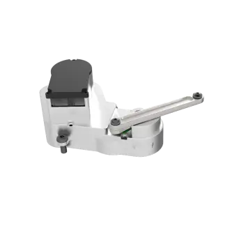
It has a three-dimensional source file, and its format contains at least one of the three formats: STEP, IGS, and STL, among which the STEP format is the most common.
Assembly reference: The center coordinates of the steering wheel and screw fixing holes.
One case is that a user downloaded an STL that only showed the appearance during the design of a quadruped robot. However, after 3D printing, he found that the orientation of the steering gear fixed ears was completely reversed. This was caused by the lack of distinction between left and right views in the drawing, so before you download, be sure to check whether there are front and back labels.
The following summary is based on industry standard sizes, which you can directly use for solution pre-research:
Most of the brush/brushless servos are applicable to the data in the above table derived from industry public technical manuals and actual surveying and mapping.
1. Prioritize looking for the product page that provides "Engineering Drawing Package", which is a requirement of the official technical archive. This product page is usually in the "Download Center" or "Support" section.You can search by keyword, and the search content is "product model + step" or "outline drawing CAD" to find relevant technical archives。
2. For specialized CAD model libraries, such as GrabCAD and 3DContentCentral, select "files and annotations are complete" as the filtering condition. Before downloading, check the comment area to see if anyone has reported "wrong hole positions".
3. For community open source projects, search "servo3D model", you will find many open source robot hardware projects. These projects will come with drawings, and these drawings have been printed and verified.
Certification tips: After obtaining the STEP document, open it with FreeCAD or Fusion360. First, measure the distance from the center of the mounting hole to the edge, and compare it with the tolerance of your structural parts.. Usually ±0.1mm is allowed. Once it exceeds ±0.3mm, it must be modified.
Misunderstanding 1: Print STL directly and ignore assembly gaps
Correction confirmation: The overall dimensions shown in the drawings are the maximum envelope range, and a gap of 0.2 to 0.5mm needs to be reserved during actual assembly operations.. It is recommended that after importing the STL into the slicing software, scale it as a whole to 99.5%.
Misunderstanding 2: Mixing drawings from different brands
Even if the torque is the same, the height of the bottom step of some brands of servos may differ by 1mm. If the screws are forcibly removed, the casing will deform. The only reliable way is to use the physical calipers in your hand to measure six key points, and then compare them one by one with the drawings.
Misunderstanding 3: Ignoring the direction of the wire harness exit
Correct it: If the location of the outlet is not marked on the drawing, the wire may be broken after installation. The solution is to download the drawings with the wire harness model, or draw an avoidance groove for the wire ends yourself.
Q: What should I do if I can’t find the drawing of a certain torque servo?
A: Go directly to the standard size drawings with similar shapes, and then modify the hole positions and total height based on the actual object you have. The modification can be completed in twenty minutes.。
Q: When the STEP file is opened, it appears messed up or damaged?
Perform automatic repair. If you use Netfabb or the 3D Builder that comes with Windows, 90% of defects can be repaired in one go.
Q: Do high-definition drawings have to be rendered in color?
A: It needs to be ruled out. Pure physical grayscale plus labeling is the most practical. Color rendering may actually hide bevel details.
Q: Why is the downloaded STL file 10 times larger than the actual size?
A: The unit is incorrectly set to inches. You need to convert the model unit from inches to millimeters in the slicing software, so that the dimensions can become normal.
Q: Can I take someone else’s drawings and directly create a mold for production?
A: No. Surveying and mapping must be carried out again, and at least 30% of the structural parameters must be modified, otherwise it will involve infringement, and the mold will not be able to be used normally due to tolerances.
It is important to emphasize again: the key value of the three-dimensional drawing of the steering gear is not that it "looks the same", but that every dimension can fit with your assembly. Don't blindly pursue the clarity of the picture, but give priority to selecting STEP files with marked tolerances.
Suggestions for action:
1. Immediately, open the CAD-related software you usually use, create a new folder called "Servo Library", and classify and place the verified drawings according to the torque category.
2. At the end of the article, there is an indication of how to obtain it. Download the standard parts package corresponding to the picture in this article. Use the three sets of basic models of 9g, 20kg, and 35kg as anchor points for your design.
3. When it comes to designing robot joints next time, you must first use drawings in the software to simulate assembly, and then use cardboard to punch holes for actual measurement. When both verifications are successfully passed, 3D printing can then be carried out.
Using the above method, you can not only find high-definition 3D drawings, but also ensure that they are accurately used in the project without errors. If you have a servo with special dimensions that needs to be reverse modeled, you can also leave a message explaining the length, width, height, and hole spacing, and I will add the corresponding surveying and mapping steps.
Update Time:2026-05-06
Contact Kpower's product specialist to recommend suitable motor or gearbox for your product.


