


TECHNICAL SUPPORT


Published 2026-03-08
Recently, many friends have asked me if they want to use the Raspberry Pi to make some small inventions, but they are stuck on how to make theservomove. Have you also encountered this kind of embarrassment - theservois connected and the code is entered, but it just doesn't move or shakes like a convulsion? Don’t worry, this is actually a hurdle that every maker will go through. Today I will take you step by step to break down this hard bone, so that theservoin your hand can obediently turn to the specified angle.
If you want to use a Raspberry Pi to control a servo, you must first understand how the two of them "talk". The servo cannot understand the digital signals of the Raspberry Pi. It only recognizes a waveform signal called PWM (Pulse Width Modulation). To put it simply, it sends electrical pulses of different widths to the steering gear to tell it to "turn to the middle position" or "turn to the far right". The Raspberry Pi itself has hardware PWM pins, but the number is limited, so many people use software simulation. You only need to connect the signal line of the servo to the GPIO pin of the Raspberry Pi, and then generate the corresponding pulse signal through programming, and the servo will be able to understand your instructions.
There are a variety of servos on the market, and choosing the wrong one can be troublesome. For getting started with the Raspberry Pi, I strongly recommend you to use the ordinary SG90 9g micro servo. This small servo is cheap and sturdy, and the voltage requirement is exactly the 5V that the Raspberry Pi can provide. If you want to do some hard work, such as controlling a robotic arm, then you have to consider this type of metal gear high-torque servo. However, I would like to remind you that the large working current of the servo may be too much for the Raspberry Pi, so it is best to power it separately. There is another point that is easy to overlook. There are two types of servos: analog and digital. For beginners, analog is enough. The control logic is simple and direct.
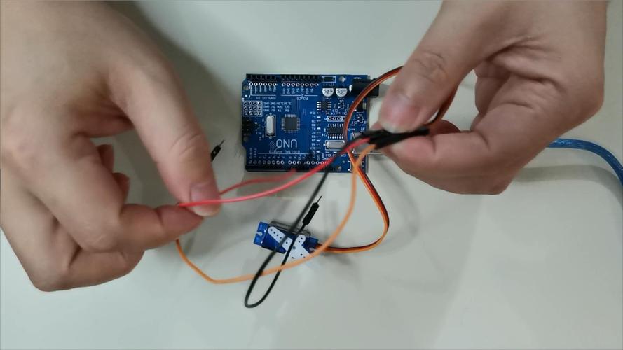
The wiring step seems simple, but many people stumble upon it. The most common mistake is to connect the positive and negative poles reversely. You can smell a sticky smell in an instant and the servo will be scrapped. You have to remember: the red wire goes to the 5V power supply, the brown or black wire goes to ground, and the yellow or orange signal wire goes to the GPIO pin. Another pitfall is insufficient power supply. The 5V pin of the Raspberry Pi has a limited output current. If more than two servos are used, the voltage will be pulled down, causing the Raspberry Pi to restart. A safe approach is to use an external power supply for the servo alone, and connect the ground of the power supply to the ground of the Raspberry Pi so that the signal can be transmitted normally.
Before you officially start writing code, you must first thoroughly understand the secrets behind the rotation of the servo. The angle of the servo is determined by a factor called "duty cycle". Let's use a vivid analogy. This is just like the faucet switch we use every day. The longer the switch is turned on, the greater the amount of water flowing out. In the PWM signal, the greater the proportion of high level, the greater the angle of rotation of the servo. For standard servos, the cycle is usually set to 20 milliseconds, and the high-level time is between 0.5 milliseconds and 2.5 milliseconds, which corresponds to the angle range from 0 degrees to 180 degrees. When using Raspberry Pi libraries, such as RPi.GPIO or more advanced ones, you need to convert these times into duty cycle values. Although the whole process sounds a bit complicated, fortunately, the library functions have generally been encapsulated for you, and you only need to directly provide the desired angle.
However, even if the library functions have been encapsulated, there are still some details worth noting during actual operation. For example, different models of servos may have slight differences in parameters, which requires you to carefully check the relevant documentation before use to ensure that the set parameters match the actual servos. In addition, when writing code, pay attention to the clear logical structure of the code, and every step must be rigorous and accurate. Although the library functions simplify many operations, if the code logic is confusing, it may still cause the servo to fail to rotate as expected. At the same time, during the debugging process, we must be good at using various debugging tools to promptly discover and solve possible problems, such as high-level time setting errors, duty cycle calculation errors, etc. Only by considering every aspect comprehensively and meticulously can we ensure that the servo can rotate accurately according to your instructions and successfully achieve the functions you expect.
If you directly let the servo jump from 0 degrees to 180 degrees, it will bounce back suddenly as if it was frightened. This will not only make the movement stiff, but also easily damage the servo gear. If you want to make the movements look good, you have to use the idea of "gradient". ️ 1. First set a starting angle and target angle. ️ 2. Calculate how many steps are needed in the middle. ️ 3. Only rotate a small amount in each step, and add a little delay in the middle. For example, if you write a loop that increases by 1 degree each time and delays by 20 milliseconds, the servo will move smoothly like a real arm. This method is particularly practical when making robots walk or robot arms grab, and the visual effect is instantly improved by several levels.
After working so hard to write the program, the servo is shaking like chaff. This situation is probably due to a power supply problem. First, check whether the power supply is stable. Use a multimeter to measure the voltage. If the fluctuation is large, add a capacitor to filter it. Secondly, it may be that the PWM signal itself is unstable, and the software simulated PWM is easily disturbed when the Raspberry Pi is running multi-tasking. The solution is to use hardware PWM pins, or upgrade the library. This library uses DMA (direct memory access) technology, and the signal accuracy will be much higher. It is also possible that the signal line is too long and is subject to interference. Try to use a shorter DuPont line, or string a small resistor on the signal line.
Seeing this, you should be confident about controlling the servo with Raspberry Pi. I'm quite curious, what interesting projects do you plan to use this skill to do? Is it a robotic arm to grab things, or is it a small robot that shakes its head? Come to the comment area to chat about your thoughts. If you find this article useful, remember to like it and share it with more friends, so that more people can join the maker family.
Update Time:2026-03-08
Contact Kpower's product specialist to recommend suitable motor or gearbox for your product.


