


TECHNICAL SUPPORT


Published 2026-03-24
Theservo"pretends to be dead" as soon as it is powered on, cannot rotate and makes no sound. This is too common in project debugging. Don't panic, 80% of the time it's not theservothat's broken, but a small mistake in the wiring, power supply or signal. Today we will go through it from beginning to end and teach you step by step how to troubleshoot the real reason why theservodoes not respond.
Check voltage and current. Servos are very picky about power supply. The rated voltage of most standard servos is between 4.8V and 6V. If you use a 3.7V lithium battery directly, of course it will not work if the voltage is not enough. What's more hidden is the lack of current. Many friends use the 5V pin on the board to power the servo. As a result, the board restarts as soon as it is started - because the current of the servo can surge to more than 1A at the moment when the servo is started, and the board cannot handle it at all. ️Solution: Equip a separate regulated power supply for the servo, or use a high-current battery pack to ensure that the voltage and current are up to standard.
Check to see if the power cord contact is weak. Sometimes when you measure the voltage and there is power, but the servo just doesn't respond, it's probably because the plug isn't plugged in tightly or the Dupont wire is broken internally. Once the positive and negative poles of the three wires used for the servo (red positive, brown negative, and orange signals) are in poor contact, the power supply will be intermittent. 1. First pull the wire end with your hand to see if it is loose; 2. Put a multimeter directly to the back of the servo plug to measure the voltage. If the voltage is normal but there is no response when plugged in, decisively try another wire.
Don’t confuse signal wires, power wires, and ground wires. The colors of the three servo wires vary from manufacturer to manufacturer. The common ones are red with positive, black and negative white signals, but there are also brown, positive, red and negative orange signals. If you connect according to your habits, reverse the positive and negative poles every minute - at worst, the servo will not turn, or at worst, the circuit board will be burned directly. The simplest method: Find the voltage and ground wire marks on the servo label, use the buzzer setting of a multimeter to test the continuity between the wire ends and the label pins, and confirm which wire is positive, which is negative, and which is the signal before wiring.
Check whether the public ground wire is connected. Many people only connect the signal wire and the positive terminal, and forget the negative terminal (ground wire). As a result, the servo will not move. Because the signal voltage is relative to the ground wire, and you do not have a common ground, the signal output by the control board is "suspended" to the servo, and it cannot recognize it at all. Remember: the control board and the servo must have a common ground, that is, connect the GND of the control board and the GND of the servo. This is the most easily overlooked detail.
First confirm whether the PWM signal is sent out. The steering gear controls the angle by PWM (Pulse Width Modulation) signal, which usually requires a frequency of 50Hz and a high-level time between 0.5ms and 2.5ms. If you write 50Hz in code but fail to check whether the pins are correct, or fail to set the duty cycle, the servo will not receive valid instructions. Use an oscilloscope or logic analyzer to capture the signal pins to see if the waveform is around the standard 1.5ms (middle value). If not, quickly go back and check the code and pin definitions.
Signal voltage and waveform must meet standards. Some 3.3V logic control boards are directly connected to the signal pins of the servo, and the servo may not recognize it - because many internal circuits of the servo are designed according to the 5V level, 3.3V may be recognized as a low level. You can try adding a resistor in series, or use a level conversion module to increase 3.3V to 5V. In addition, if the PWM waveform becomes severely distorted, such as the rising edge is too slow or has burrs, the internal chip of the servo will also be "confused". At this time, changing the shielded wire or adding a small capacitor filter can solve the problem.
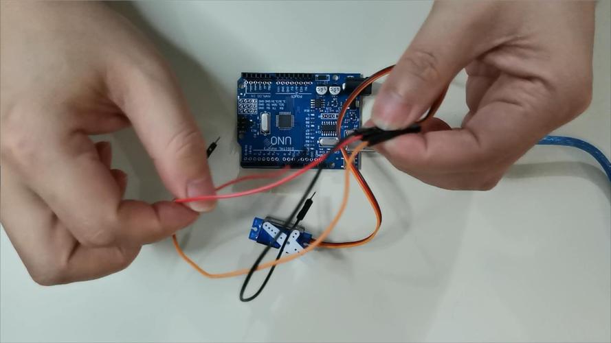
First test the servo alone. Remove it, directly connect the positive and negative terminals to the rated voltage, then take a DuPont wire, connect one end to the signal wire, and quickly touch the other end to the positive terminal of the 5V power supply - at this time the servo should make a "click" sound and turn to a certain angle. If there is no such response, it can basically be concluded that there is a problem with the motor driver chip, gearbox or the motor itself inside the servo. This test method can help you quickly distinguish whether the servo is broken or there is a problem with the front circuit.
Listen to the sound and feel the temperature. After powering on, place your hand on the servo housing to feel for slight vibrations or heat. If it keeps sizzling but won't turn, the gear may be stuck or the motor may be stuck. If there's no sound but obvious heat, it's probably because the internal circuit is short-circuited. These two situations are basically physical damage. It is recommended to replace the servo directly. Don't bother. The cost of disassembling and repairing is higher than buying a new one.
The initialization sequence is not correct. Many servos need to receive a valid PWM signal before they can enter the working state at the moment of power-on. If you supply power to the servo first and then initialize the PWM output of the control board, the blank period of a few milliseconds in between may cause the servo to enter protection mode. The correct posture is: first connect the signal line of the control board, let the PWM signal output stably, and then supply the main power to the servo. Or vice versa, the key is to make sure the signal is in place before or synchronously with the power supply.
Multiple servos are started at the same time to compete with each other for power. If you connect five or six servos at one time, all the servos will pull current at the same time at the moment of powering on, and the total current will easily exceed 5A. The power supply will be directly pulled down, and the voltage will drop below the servo undervoltage protection value. The result will be a collective strike. There are two solutions: one is to use a higher-power power supply, and the other is to write a program to initialize the servos one by one, delaying each one for 100 milliseconds before starting the next one, and staggering the starting current.
Is electromagnetic interference at play? Electromagnetic interference is particularly serious near motors, wireless modules, and switching power supplies. The signal line of the servo acts like an antenna and absorbs all interference, causing the internal chip to receive garbled instructions and either not turn or turn randomly. The solution is simple: keep the signal wires as short as possible and away from high-current wires. If conditions permit, use shielded wires, or put the control board and servo in a metal box and ground the shield.
Have you considered temperature and humidity? At low temperatures, the steering gear lubricating oil will thicken and the starting resistance will increase. If the power supply margin is insufficient, it may not be able to rotate at all. When the temperature is high, the efficiency of the internal motor of the servo decreases, and the heat dissipation of the circuit board becomes poor, which may trigger the over-temperature protection. A humid environment is more dangerous. When the circuit board gets wet, it is easy to short-circuit and interfere with the signal. Therefore, when using a servo in a special environment, it is best to choose an industrial grade or waterproof model instead of using an ordinary model servo.
When debugging the steering gear in actual projects, what other weird situations have you encountered where "the steering gear is not turning"? How was it resolved in the end? Welcome to share your experience in the comment area, and let’s avoid pitfalls together!
Update Time:2026-03-24
Contact Kpower's product specialist to recommend suitable motor or gearbox for your product.


