


TECHNICAL SUPPORT


Published 2026-03-26
When playing with theservo, the most confusing thing is looking at three wires of the same color in my hand and not knowing which one is connected to the PWM signal. Today we will clarify this most basic and critical issue, so that next time you get theservo, you can find the PWM port that controls the angle at a glance.
The three wires protruding from the steering gear have a very clear division of labor. Among them, the red wire is the positive pole of the power supply, usually connected to a voltage of about 5V; the brown or black wire is the negative pole of the power supply, which is the ground wire; and the remaining orange, yellow or white wire is the PWM signal wire we are looking for.
As long as you remember the formula "red positive, brown negative, signal color", you will be able to recognize 90% of the servos at a glance.
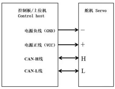
However, some servos may have different wire colors due to waterproofing requirements or special purpose considerations. How should we deal with this situation? You need to pay attention to the label on the servo housing. Generally speaking, the labels are usually marked with the three symbols S, +, and -. Among them, S represents, which is the signal line, which corresponds to the pin you want to connect the PWM signal to. Don’t worry about not being able to see clearly. If you encounter this situation, you can use a flashlight to shine on the servo shell. Most servos have such markings.
As long as you look carefully and follow the S, +, and - symbols on the servo housing label, you can accurately find the corresponding pins for connection. For example, the signal line corresponding to S is connected to the PWM pin, and the + pole and - pole are also connected to the appropriate positions according to the corresponding markings. In this way, the servo can be used correctly to ensure that it works normally in various application scenarios. Whether it is waterproofing requirements or special-purpose scenarios, its functions can be realized through accurate connections.
You may ask, why do I have to connect this wire? Why can’t I just power it directly? There is actually a small circuit board and a potentiometer inside the servo. It needs a PWM signal to tell it "which angle you should turn to." The PWM signal lets the motor in the steering gear know where to turn and how much to turn by changing the high-level duty cycle.
If you only connect the positive and negative poles of the power supply, the servo will only vibrate in place or not move at all. Because no one told it the target location, it didn't know where to stop. So this signal line is the soul that really controls the steering gear. If not connected correctly, the servo will be just a soulless motor.
It is most convenient to use a development board for testing. You first connect the red wire of the servo to 5V, the brown wire to GND, and then plug the signal wires into the pins with the "~" symbol one by one. The pins with "~" on them support hardware PWM output, such as ports 3, 5, 6, 9, 10, and 11.
Then upload a simple servo test code to make the servo swing back and forth between 0 and 180 degrees. If a certain pin is plugged in and the servo motor starts, congratulations, that is the correct PWM port. If it doesn't move, don't unplug it in a hurry. First check whether the power supply is sufficient. Some large servos cannot operate with 5V, so you need to connect an external power supply.
If you happen to have an oscilloscope handy, things get even easier. Just clamp the oscilloscope's probe firmly onto the signal and ground wires, and you'll be able to see the waveform directly and clearly. The standard servo PWM signal period is fixed at 20 milliseconds, and its high level time changes in the range of 0.5 milliseconds to 2.5 milliseconds. When the high-level time is shorter, the servo will be more inclined to the 0-degree position; conversely, when the high-level time is longer, the servo will be more inclined to the 180-degree position.
If you see a stable waveform and the high-level time is changing, then this line is definitely correct. What to do without an oscilloscope? You can also make a rough test using the frequency range of a multimeter. Although you can't see the waveform shape, you can measure the signal frequency at around 50Hz, which is also evidence.
The first common mistake is to connect the power supply backwards. The red wire is connected to the negative pole, and the brown wire is connected to the positive pole. At this time, the servo will not only not turn, but may also be burned directly. The second mistake is to connect the signal line to an ordinary digital IO port. There is no PWM output function, so the servo naturally does not respond.
The third error is more subtle and the problem is insufficient power from the power supply. The instantaneous current of some high-torque servos can reach one or two amps. If you directly use the board for power supply, the voltage regulator chip on the board will be unable to withstand such a current impact, resulting in a voltage drop. Once the voltage drops, the servo will start to vibrate randomly. At this time, an external battery or voltage stabilizing module must be used to provide power separately. Just remember to connect the ground wire to the ground wire of the control board.
When facing a situation where the power supply is insufficient, there are still some details that need to be paid attention to. For example, when selecting an external battery, you should select the appropriate battery specifications based on the power requirements of the servo to ensure that sufficient power can be stably provided. As for the voltage stabilizing module, its voltage stabilizing performance and output current capability also need to be carefully considered to ensure that a stable voltage output can be maintained when the high-torque steering gear is working, and to avoid voltage fluctuations affecting the normal operation of the steering gear. In short, correctly solving the problem of insufficient power supply is crucial for the stable operation of the steering gear.
When you first start playing with servos, there is no need to buy a high-torque servo that weighs tens of kilograms right away. You first need to look at the needs of your project, whether it is for steering a car or for a robotic arm to lift heavy objects. A common 9-gram servo has a torque of about 1.5 kilograms, which is suitable for small robots; a 20-gram servo can reach more than 3 kilograms, which is enough for general DIY projects.
Also pay attention to the type of servo. Analog servos and digital servos have different response speeds to PWM signals. It is enough for the analog servo to update the signal 50 times per second. The internal processing speed of the digital servo is faster and can accept higher frequency PWM signals. If you are using a flight controller or advanced control panel, choosing a digital servo will provide a more responsive response.
Now you know where the PWM signal line of the servo is, and you have also learned how to test and wire it. So the question is, what is your next product idea that you plan to implement using servos? Share your thoughts in the comment section.
Update Time:2026-03-26
Contact Kpower's product specialist to recommend suitable motor or gearbox for your product.


