


TECHNICAL SUPPORT


Published 2026-03-30
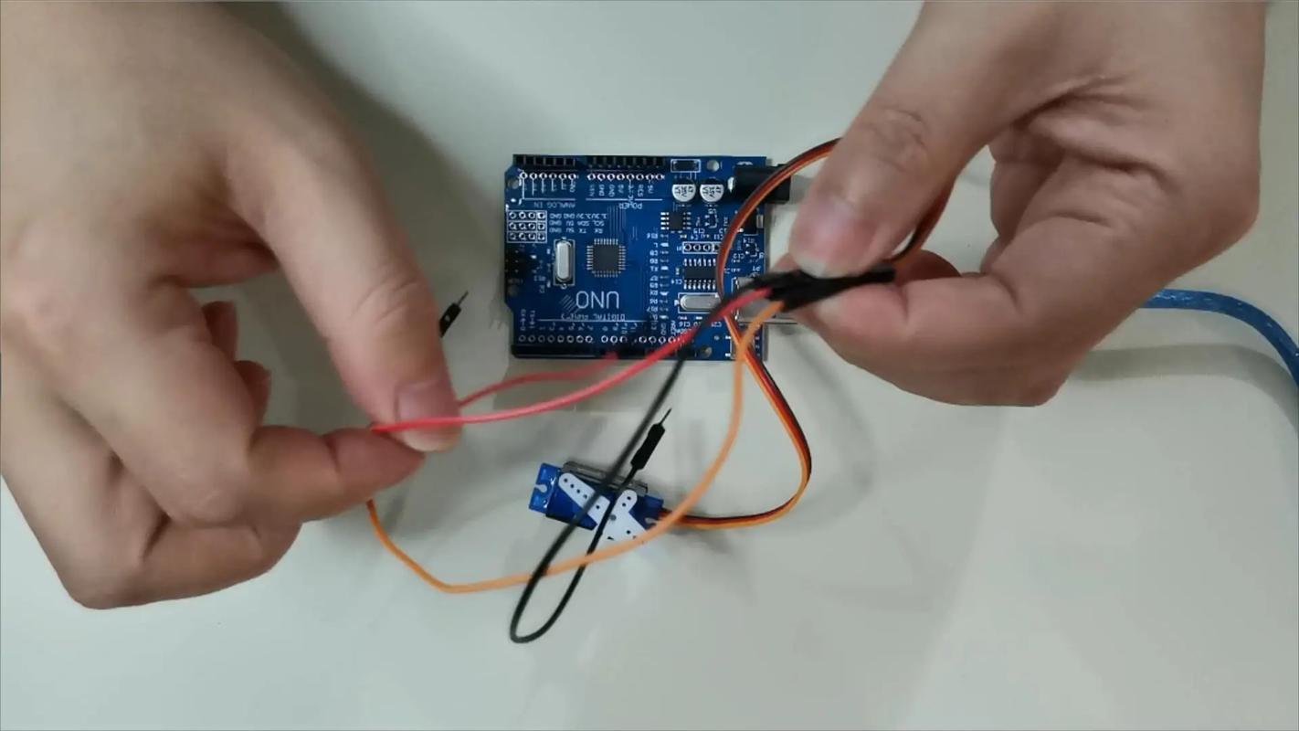
Get aservoand you will see three wires leading from the back of it. The colors are usually very uniform: red is the positive pole of the power supply, connected to 5V; brown or black is the ground wire, which is the negative pole; orange or yellow is the signal wire, used to transmit control pulses. Don't do it the other way around. Red is connected to positive, black is connected to negative, and orange is connected to the signal. Remember this formula and you won't panic. Some cheapservos may have different colors. For example, white is used as the signal line. Then read the manual or use a multimeter to test it. But most standardservos follow this color rule, so feel free to use it.
If you are still afraid of making a wrong connection, you can check the label on the servo housing. Many of them will have three symbols "+", "-" and "S" printed on them. S is the signal line. It doesn’t matter if you can’t find the label, just remember the most common combinations: red in the middle, brown and orange on both sides. Get a breadboard and a few DuPont wires, connect the power and ground wires first, and plug in the signal wire last. In this way, even if the connection is reversed, the servo will not be burned out immediately, because it will not rotate randomly without a signal. Be brave and careful, and you will get familiar with it after trying it a few times.
Many novices directly plug the red and black wires of the servo into the 5V and GND of the microcontroller, and then find that the microcontroller restarts or the servo shakes violently. This is because the current when the servo is started is very large, and the 5V output capability on ordinary microcontroller boards is limited, generally only a few hundred milliamps. The working current of a 9-gram servo can reach 200-300mA, and more than two will directly kill the microcontroller. So the correct approach is: supply the power supply to the servo separately, not through the microcontroller.
You need an external 5V power supply, such as a battery box plus two 18650 lithium batteries (stepped down to 5V) or a 5V/2A charging head. Connect the positive pole of the power supply to the red wire of the servo, and the negative pole to the black wire of the servo. At the same time, connect the negative pole of the power supply to the GND on the microcontroller. This is "common ground". The signal line is still only connected to the IO port of the microcontroller. In this way, the servo takes power from the external power supply, and the microcontroller is only responsible for sending signals. The two do not interfere with each other, and the operation is stable.
The signal line should be connected to the pin of the microcontroller that supports PWM output. PWM is pulse width modulation, which simply means it can generate square waves of different widths and high levels. The servo relies on this pulse width to decide which angle to turn to. The PWM pins of different microcontrollers are different: 3, 5, 6, 9, 10, 11 on Uno; almost all pins of ESP32/ESP32 can simulate PWM; 51 microcontroller needs to use its own timer. Check your board schematic and don't make random connections.
When connecting, please note: first write the program so that the pin outputs a 50Hz PWM signal (period 20ms). The high level time of 0.5ms corresponds to 0 degrees, 1.5ms corresponds to 90 degrees, and 2.5ms corresponds to 180 degrees. Many novices connect the signal line to the ordinary digital IO port, and then find that the servo either does not move or shakes randomly. It's because there is no PWM signal. If you are not sure which pin can be used, open the IDE and select "Example→Servo→Sweep". The default pin No. 9 is used, so you will definitely not go wrong if you follow it.
The concept of common land may seem mysterious to many people when they hear it for the first time. It's actually very simple: whether you use an external power supply to power the servo or the 5V that comes with the microcontroller, the negative poles (GND) of all devices must be connected together with wires. If it is not connected, the signal voltage sent by the microcontroller will float relative to the ground of the servo, and the servo will not be able to understand how many degrees you want it to turn. This is like two people talking, one uses centimeters and the other uses inches, but the numbers don't match. A common ground is a unified reference standard.
When actually wiring, you can use a breadboard to plug the GND of the microcontroller, the negative pole of the external power supply, and the black wire of the servo into the same row of holes. Or use a DuPont wire to directly connect the GND of the microcontroller to the negative pole of the power supply. Pay attention to the order: connect the common ground wire first, then connect the signal wire and the positive pole of the power supply. Developing this habit can prevent a lot of weird problems. There are many cases of servos shaking, not turning, or turning randomly. In the end, after checking again and again, we just forgot to share the ground. This one thread saves you three hours of troubleshooting bugs.
After connecting the wires and burning the program, the servo did not respond at all. Don't worry, check in order: first step, check the power supply voltage. Use a multimeter to measure whether there is about 5V between the red line and the black line of the servo. If it is lower than 4.5V, the servo may not start. The second step is to see if the common ground wire is loose. Plug and unplug the common wire again. Many times it is a bad contact on the breadboard. The third step is to confirm that the pin you selected indeed outputs the PWM signal. Take a look with an oscilloscope or logic analyzer, if not, try changing the pins.
If the servo clicks but doesn't turn, the load may be too heavy. Gently pry the servo arm with your hands to see if it is stuck. It is also possible that the pulse width range is wrong. For example, your program sends 0.5ms to 2.5ms, but the servo actually requires 0.7ms to 2.3ms. This can be solved by modifying the minimum and maximum pulse values in the code. The last situation: the servo itself is broken. Try changing the servo. If the new one can turn, then the old one is burned out. Usually the servo burns out because the voltage exceeds 6V or the signal wire is connected reversely.
Controlling the servo is the easiest because of the ready-made Servo library. Open the IDE and click "Project→Load Library→Servo". Write four lines of code:# introduces the library,Servo ;creates the object,.(9);binds pin 9,.write(90);turns the servo to 90 degrees. Put these in the setup function, and the servo will immediately turn to the middle position after uploading. If you want to swing back and forth, write.write(0); delay(1000); .write(180); delay(1000);in the loop.
Note: The Servo library will occupy the timer. If you use other functions that require precise timing at the same time, there may be conflicts. At this time, you can switch to PWM direct control, usingIt doesn't work because its frequency is wrong. A better way is to use.()and give the microsecond value directly. For example, 1500 microseconds corresponds to 90 degrees. In addition, do not frequently send new commands when the servo is rotating. Leave more than 200 milliseconds for it to arrive. After mastering these few lines of code, you can already control most standard servos.
Have you ever encountered a situation where the servo vibrates wildly or makes a hissing sound after being connected? Share your wiring experience in the comment area. The one with the highest likes will help you troubleshoot the problem remotely.
Update Time:2026-03-30
Contact Kpower's product specialist to recommend suitable motor or gearbox for your product.


