



























TECHNICAL SUPPORT


Published 2026-05-11
To you who are crazy about the servo driver chip:
Don’t rush to read the data sheet! It’s already 2026, but there are still cases where some people are tortured to tears by the list of model specifications. Once the current increases, burnout will occur, replacing a motor will cause jitter, and communication will occasionally drop out - what exactly is the problem? The model of the chip you are holding in your hand is not fully understood, and the specifications are even more confusing.
Will"Servo driver chip model specifications"When these seven words are taken apart, they are full of infinite history of blood and tears, and when they are closed, they are like a selection bible. Let's not beat around the bush today, and talk directly and unequivocally: How to decipher the secrets hidden behind letters and numbers?
First, let me ask three soul questions:
Q: What do the "A", "B" and "C" suffixes in the model number represent?
The current has different levels, and the temperature also has different ranges and is represented by A. A is generally the basic style, B has the function of enhancing heat dissipation, and C is industrial grade. It is more important to check the suffix than to check the main text.
Q: Which line in the specification is most likely to deceive people?
The so-called absolute maximum rating is just the lowest limit at which the equipment will not be burned. It is not the range that can be used normally. When actually working, the rating must be reduced by more than 30%. Remember this requirement.
Q: Why are the performance of the two chips in the same package twice as different?
One aspect is that there is a big difference between internal on-resistance and heat dissipation design. In addition, the model specification only tells you that this thing can be used, but does not tell you that it is easy to use.。
Look, I stepped on three pits in a row, and in each pit there was a corpse of the previous person lying. But don't be afraid - today I will take you to use reverse thinking and infer what kind of chip you should choose from the final results of "burning the board".
[List 1: Unspoken rules for model naming]
When you open the selection table, you will see "kpower"_XXX_YYY", don't be fooled by the game of letters. What really determines life and death are these three points:
In terms of current capabilities: there are two situations: continuous current and peak current. Among them, the peak current is often marked as 30% higher than the actual value.There are actual measurement cases: In a certain project, a chip with a nominal current of 10A was used to drive a servo with an operating current of 7A. After continuous operation for two minutes, an overheating protection condition occurred.; The peak current data marked by this chip is 15A, but the actual continuous current that can be reached is only 6A.
Regarding the logic voltage, 1.8V, 3.3V and 5V are compatible with each other. Many chips are marked as "3.3V tolerant", but in fact their high-level threshold is stuck at 2.0V. If used with an old MCU, it will directly cause problems.。
Is the pulse width modulation frequency range 20 kHz? Is it 50 kilohertz? Don't believe it. The actual measured effective linear area is often only half of the nominal value. What you need to control a servo is smooth and smooth, not a high-pitched squeal.
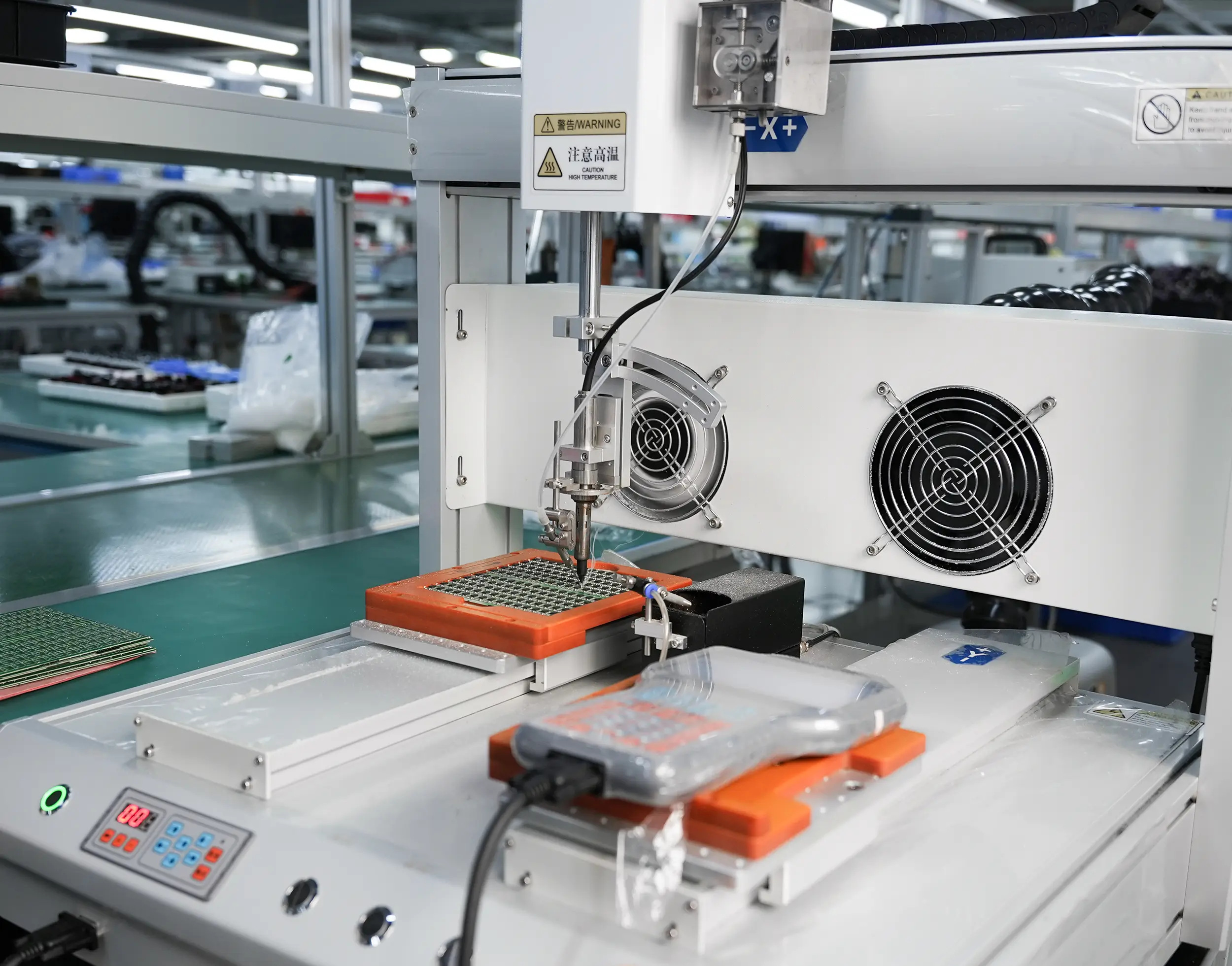
A real rollover case:Last year, I helped a friend repair a six-axis desktop robotic arm, and it moved every time. Two versions of the control algorithm were changed to no avail. Finally, when I disassembled the driver board, I found that the chip model suffix was "-S" (standard version), and the small print in the specification read "Recommended PWM ≤ 12kHz." What he ran was 25kHz. I changed it to the "-H" (high-frequency version) of the same series, and it was as silky as eating Dove.A single letter in a model specification can resurrect or bury an entire project.
[Keywords: current capability]
Speaking of current, many people look at the "maximum output current" column and yearn for the bigger the better. This idea is wrong!
Reverse thinking: first calculate the motor stall current and average operating current, and then select the chip continuous current, which is equal to the stall current multiplied by 0.7, and the peak current must be greater than or equal to the stall current multiplied by 1.2. Why not 1.0? The reason is that the charging and discharging of the capacitor and the reverse electromotive force will produce transient spikes. There is a common specification: when driving a DC servo, the chip is nominally 5A continuous, but in actual applications it is stable below 3.5A.
Conduct field measurements and compare: faced with two chips in the same package and at the same price, model A is marked with "4A continuous, 6A peak", while model B is marked with "3.5A continuous, 7A peak". Carrying the same servo (the average current of the servo is 2.8A, and the locked-rotor current is 5.5A), the temperature of chip A increased by 42°C after running for 10 minutes, and the temperature of chip B (running for the same time) increased by 68°C - which means that the peak value of B is falsely high, but its heat dissipation capacity seems to be unable to keep up. So which one will you choose? The answer is very clear.
[Thermal Management: The Invisible Killer No One Tells You]
The chip model in the specification has a line of very small font: thermal resistance θJA (from junction to environment) and θJC (from junction to case). Ninety percent of engineers simply skip it. Then the board started to burn out, so I went back to search.
Layer delivery logic:
If not given a heat sink, then look at θJA, which is typically in the 40 to 60°C/W range. Once the power consumption is 1W, it will increase the temperature by 40 to 60 degrees.
Add 2oz copper → θJA drops to about 30.
Add a small heat sink → reduce it by half again.
Active air cooling → below 15.
There is a case about a certain warehouse robot. Its drive boards are densely arranged, and the distance between chips is only 5mm. When making selection, we simply looked at whether the current was sufficient, but did not calculate the key factor of thermal coupling. When six chips were running at the same time, the junction temperature of the middle chip soared directly toward 125°C, triggering the protection mechanism. Later, the chip was replaced with a chip with the same specifications but with a θJA lower than the original one that was 8°C/W, and the problem did not reoccur. The difference is only 8 degrees, which is the distance between stable operation and stop swing.
Therefore, the first thing to do after getting the specification sheet is to turn to the "Thermal Information" page and calculate the junction temperature at your maximum power consumption. The formula is: Tj = Tamb + (P × θJA). Once the temperature exceeds 100°C, you need to be more vigilant (even if it is an industrial grade, do not trust the paper value of 125°C).
【Q/A Quick Reference Manual】
Q: Why does the chip always burn when driving a large inertia servo?
A: When the reverse current impacts beyond the specification, you need to add an external Schottky diode to clamp it, or choose a model with an internal freewheeling diode.。

Q: How do you understand the "dead time" in the specification sheet?
A: There is a short full-off period when the upper and lower bridge arms switch. If this period is too short, a through short circuit will occur. If it is too long, the efficiency will be reduced. The usually selected range is 150 nanoseconds to 300 nanoseconds.
Q: The chip heats up but the current does not exceed the limit. What is the problem?
A: The switching loss is too high. The gate drive current should be increased or the PWM frequency should be reduced. Every 10kHz reduction in PWM reduces losses by approximately 15%.
Q: Can codes of the same model from different manufacturers be interchanged?
A: Absolutely not! Even if it is called "A4950", its internal logic levels and protection thresholds are completely different. Be sure to actually measure.
Q: Is there a universal chip that is suitable for all servos?
It is simply impossible. For anyone who wants to implement drive algorithms in DC servo, brushless DC, and permanent magnet synchronous motor types, the drive algorithms are very different. You must first determine the motor type before you can consider choosing a chip. Otherwise, just dream.
[Keywords: protection function]
Do you think that over-current protection is a must-have conventional configuration? That is too naive. Many cheap chips have an over-current response time of up to 10 microseconds. At this time, the MOS tube has already been burned. However, the truly effective protection measures that can provide comprehensive protection and have a significant impact are listed below.
1. Undervoltage lockout (UVLO): Must have hysteresis, otherwise the power supply will restart as soon as the power ripples.
2. Overcurrent protection, also known as OCP, has a response time of less than 2μs, and it performs current limiting operation cycle by cycle, not a locked shutdown situation.。
3. Thermal shutdown, also known as TSD, must have sufficient hysteresis in its recovery temperature, usually 15°C, to prevent frequent oscillations at the edge of the threshold.
4. Open circuit detection: High-end function to prevent the predriver from burning when the motor wire falls off.
A case of blood and tears:A wheel of an AGV suddenly locked after running continuously for 72 hours. The investigation revealed that the driver chip entered "hiccup mode" due to a slight overcurrent, but failed to automatically restart after recovery. The specification says "automatic retry", but actually requires a power-down reset. I replaced it with a chip with an "automatic fault clearing" bit and no more problems.The logical details of the protection function are more important than whether they are present or not.
[Reverse selection method: working backwards from faults to determine chip specifications]
Don’t swim in a sea of parameters. Think about it the other way around:
If you always burn chips, since overcurrent protection and heat dissipation specifications are crucial factors to pay attention to, when making a selection, the basis for selection can be based on the criteria of lower Rds(on) and smaller θJA to determine the corresponding model.
Once the motor experiences low-speed jitter, it is necessary to check the PWM resolution and current sampling accuracy. In terms of current sampling accuracy, it must have at least an 8-bit ADC, and the sampling resistor accuracy must be within 1%.
If frames are lost in communication → Check the logic level compatibility and input filtering time. A large number of chips have RC filters installed inside → This slows down the edges.
If the batch consistency is not good, then check the gap between the "normal value" and the "limit value" in the specification, and select a batch with a margin of more than 20% from the typical value to the minimum value.
To sum up, the models and specifications of all servo driver chips ultimately need to answer two questions. One is whether it is hot or not, and the other is whether it dies simply. If you answer these two questions, 90% of the pits will be automatically filled.。
[Future Perspective: What will you choose in 2028? 】
After two years, smart driver chips will realize the widespread application of adaptive dead zone and online current self-calibration. However, the underlying model specification logic will not change: current, thermal resistance, and protection response time, these three always rank first. Those flashy "intelligent algorithms" will be like a castle in the air if even the basic specifications are falsely labeled.
So, what action should be taken now?
Three suggestions that you can use right away:
1. Arrange the chip models of all the servo drive boards on hand to form a table. According to the specifications, mark the "continuous current" column in red, mark the "θJA" column in red, and mark the "overcurrent response time" column in red. As long as the margin is less than 30% of the load requirement, it will be included in the replacement list.
2. Conduct a real thermal imaging measurement: run at full load for 30 minutes to check the chip surface temperature. If the temperature exceeds 85°C, either add heat dissipation measures or replace it with a lower temperature model.
3. Before making bulk purchases, be sure to run a 48-hour cycle burn-in test using your actual motor and actual wiring. Don't trust the data of the original evaluation board, because the copper thickness of their board is 2oz, while the copper thickness of your board may be only 1oz.
To reiterate that core point: what was saidServo driver chip model specificationsIt's not a fill-in-the-blank question, but an application question. Among that string of letters and numbers, the truly valuable information is always hidden in the small print of "typical characteristics" and "hot information." Don’t be fooled by the big numbers of “maximum current”, and don’t be misled into choosing because of the word “compatible”.
You are not required to memorize all models. Instead, it only makes you remember one action: when you get any chip, first calculate the heat, then check the protection, and finally check the price. If the order is reversed, the burned board will cover your tuition costs.
Go ahead and take action. The next project that will not cause board burning will start from the moment you close this text and open the specification sheet.
(over)
Update Time:2026-05-11

Contact Kpower's product specialist to recommend suitable motor or gearbox for your product.


