



























テクニカルサポート


発行済み 2026-07-16
簡単な回答
正確な情報を見つけるSolidWorks ファイル標準用サーボAdafruitマイクロのようなものサーボ独自の公差があるため、可能になることはほとんどありません。エンジニアは汎用モデルに依存するのではなく、シャフト直径、取り付け穴の間隔、トルク仕様などの重要な寸法を公式データシートと照合して検証する必要があります。不正確な CAD ファイルを使用すると、アセンブリエラーやパフォーマンス障害が発生します。正確なモーション コントロールの統合が必要なプロジェクトの場合、検証済みの技術図面を提供するメーカーと協力することで、互換性が確保され、設計リスクが効果的に軽減されます。
既製のコンポーネントをカスタム機械設計に統合するという課題は、多くの場合、欠落している部分、つまり正確な CAD データから始まります。多くのエンジニアは特定の情報を検索しますSolidWorks ファイルAdafruit micro などの人気製品のフォーマットサーボ、正確なジオメトリに即座にアクセスできることが期待されます。ただし、商用サーボ メーカーは、知的財産と絶え間ない製品の反復のため、ネイティブ CAD モデルを公開することはほとんどありません。ユーザーが生成したモデルや近似モデルに依存すると、組み立て、トルク計算、空間計画に重大な誤差が生じる可能性があります。期待されるデジタルの可用性と物理的な現実との間のこの乖離により、設計段階で摩擦が生じ、プロジェクトのタイムラインが遅れ、プロトタイピングのコストが増加する可能性があります。
自動化を成功させるには、認定された技術文書が一般的な 3D モデルよりも重要である理由を理解することが不可欠です。中心的な問題は、サーボの統合に必要な精度にあります。取付穴位置や軸公差にわずかなズレがあると、位置ずれや振動、早期故障の原因となります。したがって、既製のファイルの検索から、公式仕様を通じて重要なパラメータを検証することに焦点を移す必要があります。このアプローチにより、選択したコンポーネントがより広範な機械システムにシームレスに適合し、製品のライフサイクル全体にわたって構造の完全性と動作の信頼性が維持されます。
01汎用 CAD モデルが危険な理由
多くのオンライン リポジトリでは一般的な電子機器の 3D モデルが提供されていますが、これらは多くの場合近似値です。重要な内部詳細が欠如していたり、寸法公差が不正確である場合があります。メカニズムを設計する際、汎用モデルが物理的な製品と正確に一致すると仮定するのは危険な賭けです。
寸法の不正確さ: 外形寸法は正しく見えるかもしれませんが、内部の歯車列のクリアランスとシャフトの振れが正確にモデル化されることはほとんどありません。
許容差の欠落: CAD ファイルでは、密着したアセンブリにとって重要な製造公差が無視されることがよくあります。
動的ロードエラー: 静的モデルでは動的力が考慮されていないため、モーターのサイズ決定が不正確になります。
互換性の問題: ピン配置と電気接続が機械 CAD ファイルで表現されることはほとんどないため、後で配線の競合が発生します。
設計者は、未検証のファイルをダウンロードする代わりに、製造元から詳細なデータシートと技術図面を入手することを優先する必要があります。これらの文書は、正確なシミュレーションと物理プロトタイピングに必要な事実の基礎を提供します。
02重要な仕様マイクロサーボ統合
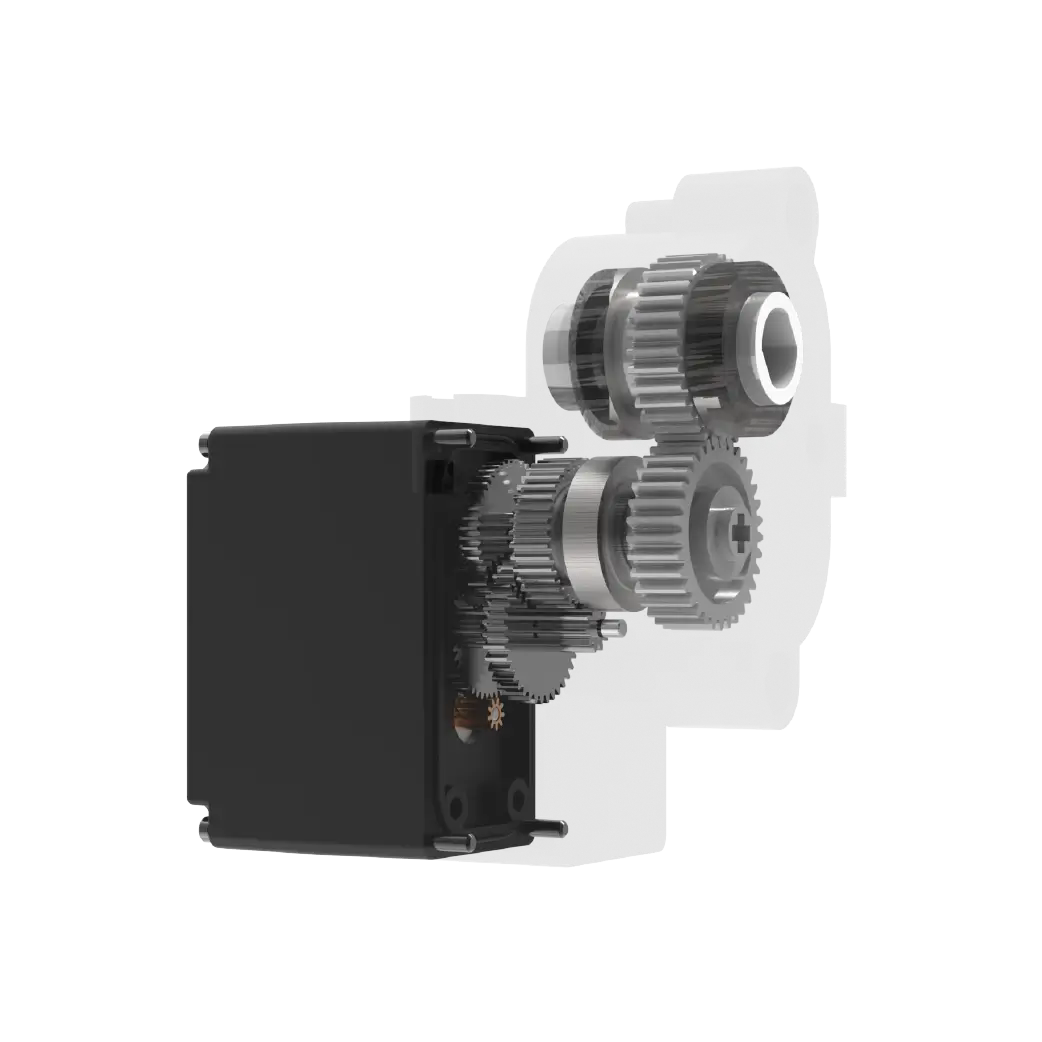
を選択するときは、マイクロサーボアプリケーションにとって、主要な技術パラメータに焦点を当てることは、完璧な CAD モデルを見つけるよりも価値があります。次の仕様は、特定の状況でサーボがどのように動作するかを定義します。
1. トルク出力: kg-cm または oz-in で測定され、耐荷重が決まります。サーボが失速することなくピーク負荷を処理できることを確認します。
2. 動作電圧: 標準マイクロサーボ多くの場合、4.8V ~ 6V で動作します。損傷を防ぐために、電源との互換性を確認してください。
3. 回転速度: 60 度あたりの秒数で定義されます。速度が速いほど、より高い電流と強力な冷却が必要になる場合があります。
4. 取付寸法: 本体サイズ、ネジ穴間隔 (標準マイクロの場合は通常 18mm x 18mm)、シャフト径を確認してください。
5. 制御信号: ほとんどは 50Hz 周波数の PWM 信号を使用します。パルス幅の範囲 (通常は 0.5ms ~ 2.5ms) がコントローラと一致していることを確認します。
これらの要因は機械設計に直接影響します。たとえば、より高いトルク要件が必要になると、より大きなギア比が必要となり、アセンブリ全体のサイズと重量に影響を与える可能性があります。
03SolidWorks ファイルを使用せずに互換性を確認する方法
直接の連絡先が見つからない場合は、SolidWorks ファイル場合でも、検証済みのデータに基づいてカスタム モデルを作成することで、高い精度を実現できます。このプロセスには、メーカーの技術文書から主要な寸法を抽出し、それを自分でモデル化することが含まれます。
ステップ 1: データシートを入手する: サプライヤーから公式 PDF をダウンロードします。 「外形寸法」と「電気的特性」をご覧ください。
ステップ 2: 主要なプロファイルをスケッチする: 正確な本体の幅、高さ、奥行きを持つ 2D スケッチを作成します。取り付けフランジの形状に注意してください。
ステップ 3: シャフトのモデル化: 出力シャフトを正しい直径と長さで押し出します。キー溝または止めネジがある場合は、それも含めます。

ステップ 4: インターフェースを定義する: 信号コネクタと電源端子の基準点を追加して、アセンブリ内で適切なケーブル配線を確保します。
ステップ 5: 検証する: 入手可能な場合はモデルを物理的な製品と比較するか、他の信頼できる情報源と照合してください。
この方法により、デジタル ツインが現実世界のコンポーネントを確実に反映し、製造中の組み立てエラーのリスクが軽減されます。
04比較: 既製サーボとカスタムソースサーボ
適切なサーボ タイプの選択は、特定のアプリケーションのニーズによって異なります。以下は、標準のマイクロサーボと特殊なソリューションのどちらが優れているかを判断するのに役立つ比較です。
ほとんどの趣味や軽工業用途では、標準マイクロサーボで十分です。ただし、高速または高精度のタスクの場合は、初期コストが高くても、産業グレードのソリューションに投資した方が、長期的にはより良い結果が得られる可能性があります。
05マイクロサーボの選択に関するよくある質問
Q: CAD ファイルの代わりに 3D プリントされたモデルを使用できますか?
A: いいえ、3D プリントされたモデルには、機械設計の検証に必要な精度が欠けています。公式仕様から派生したベクトルベースの CAD モデルを常に使用してください。
Q: マイクロサーボの標準的な取り付けサイズはどれくらいですか?
A: ほとんどの標準的なマイクロ サーボは 18mm x 18mm の取り付け穴パターンを使用しますが、これを特定のデータシートで必ず確認してください。
Q: サーボがスペースの制約に適合するかどうかを確認するにはどうすればよいですか?
A: 技術図面からエンベロープの寸法 (長さ、幅、高さ) を測定し、ケーブルと熱放散のための余分なスペースを考慮してください。
Q: データシートがある場合、SolidWorks ファイルを無視しても安全ですか?
A: はい、データシートの正確な寸法を使用してパーツを手動でモデリングする限り、可能です。多くの場合、これはダウンロードされたファイルよりも正確です。
Q: ロボットアームを動かすにはどのようなトルクを選択すればよいですか?
A: 完全に伸ばした状態での静荷重を計算し、動的加速力を考慮して 1.5 ~ 2.0 の安全係数を掛けます。
Q: 複数のサーボに特定の電源が必要ですか?
A: はい、サーボは起動時に大電流を消費します。すべてのアクティブなサーボの合計電流を同時に処理できる安定化電源を使用してください。
06長期的なより良い意思決定を行う
適切なモーション コントロール コンポーネントを選択するには、デジタル ファイルを見つけるだけでは不十分です。機械的制約、電気的要件、および期待されるパフォーマンスを完全に理解する必要があります。便利ではあるが不正確な可能性がある CAD モデルよりも検証済みの技術データを優先することで、堅牢で信頼性の高い設計が保証されます。
正確な統合とサポートが必要なプロジェクトの場合は、カスタマイズされたソリューションを提供できる専門家に相談することをお勧めします。キロパワーサーボは、さまざまなタイプのサーボに対して包括的な技術サポートと検証済みの仕様を提供します。当社のエンジニアリング チームに連絡して、お客様の特定の要件について話し合い、次の自動化プロジェクトに合わせた推奨事項を受け取ります。
更新時間:2026-07-16


