
























テクニカルサポート


発行済み 2026-07-11
簡単な回答
あサーボステアリングカーの構造を使用しますサーボ車輪付き車両の方向を制御するためにステアリングリンケージに接続されたモーター。のサーボコントローラ (通常はマイクロコントローラまたは RC 受信機) から信号を受信し、出力アームを特定の角度に回転させ、車輪を回転させるタイロッドを押したり引いたりします。主要なコンポーネントには、サーボ モーター、ステアリング アーム、タイロッド、ナックル、ホイール ハブ アセンブリが含まれます。適切なアライメント、サーボトルク定格、および機械的利点によって、ステアリングの精度と信頼性が決まります。ほとんどの小規模なロボットまたは RC カーの用途では、トルク 4 ~ 6 kg・cm の標準的なアナログまたはデジタル サーボで十分ですが、重量のある車両や高速車両の場合は、より高いトルクと金属ギアが必要になります。
01導入
ステアリング システムが動作中に故障すると、単に不便であるだけでなく、コンポーネントが損傷し、開発時間が無駄になり、プロジェクトが数週間も遅れる可能性があります。多くのエンジニアや愛好家がサーボステアリング車の構造機械的な詳細がどれだけ重要であるかを初めて過小評価することになる。価格やサイズに基づいてサーボを選択しますが、数回走行した後に車がアンダーステアになったり、サーボがストールしたり、リンケージが固着したりすることがわかります。実際のコストはサーボ自体ではなく、トラブルシューティング、再設計、部品交換に費やした時間の損失です。サーボ ホーンからホイール ハブに至るまで、ステアリング システムの各部分がどのように連携するかを理解することは、これらの問題を回避し、予測通りに反応する車を構築するのに役立ちます。
02目次
1. サーボステアリングカーの構造の中核となる部品
2. ステアリングリンケージがどのように動きを伝達するか
3. アプリケーションに適したサーボの選択
4. 一般的なステアリングジオメトリ構成
5. 組立前に確認すべき主な仕様
6. サーボステアリングの設計について購入者からよく聞かれる質問
7. 長期的なより良い意思決定を行う
03サーボステアリングカーの構造の中核となるコンポーネント
のサーボステアリング車の構造回転運動をホイールの直線運動に変換するために、いくつかの機械的作動部品が一緒になって構成されています。
サーボモーター– PWM信号入力に基づいて指令された角度に回転するアクチュエータ。出力軸はサーボホーンに接続されます。
サーボホーン– サーボ出力スプラインに取り付けられたアーム。回転運動をリンケージシステムに伝達します。
ステアリングアームまたはベルクランク– サーボホーンからタイロッドへの力の方向や大きさを変えるレバー。
生まれた人たち– ステアリングアームをホイールナックルに接続する剛性リンク。ハンドルを押したり引いたりして操縦します。
ナックルまたはアップライト– ホイールハブを保持し、ホイールがキングピンまたはボールジョイントを中心に回転できるようにする回転アセンブリ。
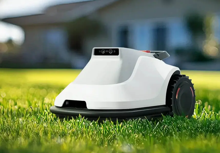
ホイールハブとベアリングアセンブリ– ホイールをサポートし、ステアリング時の摩擦を軽減します。
各コンポーネントは、車両の重量、速度、動作環境に合わせて適切なサイズにする必要があります。単一の部品の不一致は、ずさんなステアリング、過度の摩耗、または機械的故障を引き起こす可能性があります。
04ステアリングリンケージがどのように動きを伝達するか
ステアリング リンケージは、サーボとホイールの間の機械的なブリッジです。信頼性の高いパフォーマンスを実現するには、その形状を理解することが重要です。
サーボが時計回りに回転すると、サーボホーンがステアリングアームを前方に引っ張ります。その動きがタイロッドを通ってナックルに伝わり、ホイールが回転します。逆回転するとホイールが反対方向に押されます。
サーボの回転と車輪の角度の比率は、レバーアームの長さによって決まります。サーボ ホーンを長くすると、サーボ回転 1 度当たりのホイール トラベルが増加しますが、機械的な利点が減少します。ホーンを短くするとホイールのトルクが増加しますが、同じ回転でより多くのサーボ回転が必要になります。
ほとんどの人にとってサーボステアリング車の構造、1:1 またはわずかに漸進的な比率は、応答性とトルクのバランスが良好です。車両が重い場合や高速で走行する場合、メカニカルアドバンテージが高くなると、急旋回時にサーボが失速する可能性が低くなります。
よくある間違いの 1 つは、リンケージをあまりにも傾けて組み立てることです。ボールジョイントまたはネジ付きロッドエンドにより、トー角の微調整が可能です。タイロッドエンドに 1 ~ 2 mm の遊びがあるだけでも、高速走行時にはステアリングのふらつきが顕著になります。
05アプリケーションに適したサーボの選択
正しいサーボを選択することは、サーボを構築する上で最も重要な決定です。サーボステアリング車の構造。間違った選択をすると、制御不良、過熱、または機械的損傷につながります。
定格トルク– kg·cm または oz·in で測定されます。一般的な小型RCカー(1~2kg)の場合、3~5kg・cmが必要です。大型車や重量車(5~10kg)の場合は8~15kg・cmが必要です。計算された要件を少なくとも 20 ~ 30% 上回るヘッドルームを持つサーボを常に選択してください。
スピード– 60 度あたりの秒数で測定されます。サーボを高速化すると (0.08 ~ 0.12 秒/60°)、ステアリングの応答性が向上しますが、消費電流は増加します。ほとんどの実用車には、より遅いサーボ (0.15 ~ 0.20 秒/60°) で十分です。
ギア材質– プラスチック製ギアは静かで安価ですが、衝撃を受けると剥がれます。オフロード車両、高速車両、重量車両には金属ギア(スチールまたはチタン)が不可欠です。
Analog vs. digital – Analog servos are simpler and cheaper but have less holding torque and can drift. デジタルサーボ provide faster response, higher holding torque, and better precision, which matters for applications requiring consistent steering angle.
動作電圧 – Most servos run on 4.8–6.0 V. Higher voltage increases torque and speed but generates more heat. Verify your power supply and servo specifications match.
A buyer checklist can help you compare options quickly:
The layout of the サーボステアリング車の構造 affects turning radius, stability, and tire wear. Three configurations are widely used.
Ackermann steering – The inner wheel turns at a sharper angle than the outer wheel, reducing tire scrub during turns. This geometry is best for vehicles that need stable cornering on paved surfaces. The servo is typically mounted centrally and connected via a drag link to both wheels.
Parallel steering – Both wheels turn at the same angle. This is simpler to build and works well for slow-speed robots or vehicles that pivot on the spot. However, tire wear increases during sharp turns.
Crab steering – All wheels turn in the same direction, allowing the vehicle to move sideways. This requires multiple servos and a more complex linkage but offers unique maneuverability for specialized applications.
For most builders, Ackermann geometry provides the best balance of stability and turning performance. If you are prototyping, start with a simple parallel setup and adjust after testing.
Before you mount the servo and connect the linkage, verify these five parameters:
Servo mounting bolt pattern and dimensions – Ensure the servo fits the bracket or chassis cutout. Standard sizes are 23×12 mm (micro), 40×20 mm (standard), and 54×30 mm (large).
Servo horn spline count and shape – Most servos use 25-tooth or 24-tooth splines, but compatibility varies. The horn must fit securely without play.
Tie rod length range – Adjustable tie rods with threaded ends allow fine toe adjustment. Minimum and maximum length should cover the required wheel angle without binding.
Wheelbase width and turning radius requirement – Narrower wheelbases need less servo torque but may be less stable at speed. Calculate the maximum turning angle needed for your operating space.
Clearance around the linkage – The steering arm and tie rod must not hit the chassis, suspension arms, or wheels at full lock. Dry cycle the system before final assembly.
Checking these items before assembly saves time and prevents rework. A few minutes of measurement can avoid hours of troubleshooting later.
Q: Can I use a standard RC servo for a 5 kg robot car?
Yes, but you will need a servo with at least 10 kg·cm torque and metal gears. Standard plastic-gear servos will strip under load. Verify the mounting bracket and power supply can handle the continuous draw.
Q: What is the difference between analog and digital servos for steering?
Digital servos update the motor control signal more frequently, providing faster response, higher holding torque, and better precision. Analog servos are less expensive but may drift or lag under load. For precision steering, digital is recommended.
Q: How do I prevent steering linkage binding?
Ensure all rod ends or ball joints move freely without forcing the servo to its mechanical stop. Use spacers or washers to align the linkage in a single plane. Test the full range of motion before applying power.
Q: What causes servo jitter in a steering system?
Jitter is often caused by insufficient power supply voltage, electrical noise from nearby motors, or a weak signal from the controller. Use a separate BEC or voltage regulator for the servo, and keep servo signal wires away from high-current power cables.
Q: How often should I replace servo gears?
Check after every 20–30 hours of operation or after any hard crash. If the servo makes grinding noises, loses centering accuracy, or has visible play, replace the gear set immediately to prevent further damage.
Q: Is waterproofing necessary for a servo steering car structure?
Not always, but if you operate on wet grass, mud, or near water, choose a servo with an IP rating of at least IP67. Standard servos can fail quickly if moisture enters the gear train or electronics.
Q: What happens if the servo torque is too low?
The servo may stall during turns, causing the vehicle to understeer or stop responding. In extreme cases, the servo motor can overheat and fail permanently. Always calculate torque requirements with a safety margin.
Q: Can I use one servo to steer two wheels?
Yes. A single servo connected via a drag link or tie rod to both wheels is a common design. The servo must be centered and the linkage symmetric to ensure equal turning in both directions.
Q: Does servo speed matter for steering accuracy?
Yes, but only up to a point. Faster servos reduce lag between command and wheel movement, which helps at high speeds. For slow-moving robots or utility vehicles, speed is less critical than torque and holding strength.
Q: How do I set the servo center position?
Send a 1500 µs PWM signal (typical center) and mount the servo horn perpendicular to the linkage. Adjust the tie rod length until both wheels point straight ahead. Fine-tune using the transmitter trim if needed.
Building a reliable サーボステアリング車の構造 comes down to understanding the mechanical relationship between each component. A well-matched servo, properly aligned linkage, and correct geometry give you consistent steering performance without constant adjustments or failures.
Start by calculating your vehicle weight and operating speed. Choose a servo with sufficient torque headroom, metal gears if impact is likely, and digital control if precision matters. Verify the linkage geometry before final assembly, and test the full steering range under load.
If you are evaluating multiple servo options or need help matching components to your specific application, contact our engineering team with your vehicle specifications. We can recommend compatible parts and help you avoid common design pitfalls.
Update Time:2026-07-11


