
























テクニカルサポート


発行済み 2026-07-12
簡単な回答
あPWMサーボドライバーボードは制御信号を正確なモーターの動きに変換しますが、すべてのボードが同じ精度、熱管理、または多軸同期を実現できるわけではありません。間違ったボードを選択すると、特に複数のボードでジッター、過熱、またはモーション シーケンスの失敗が発生することがよくあります。サーボロボット工学、CNC、産業オートメーションなどのアプリケーション。適切なボードは、電圧範囲、信号解像度、更新速度、熱設計に適合する必要があります。購入する前に、総所有コストを増加させるフィールド障害を回避するために、ボードの PWM 周波数、チャネルごとの定格電流、および保護機能を確認してください。
01導入
毎年、制作チームが数千ドルを失っているのは、サーボは欠陥がありますが、PWMサーボドライバーボード彼らが選択したのは、現実世界の負荷を処理できないということです。ピックアンドプレースラインでの腕の動きがぎくしゃくする。長時間の稼働中に過熱する。サーボがサイクルの途中で位置を失う。これらの症状がモーター自体を示していることはほとんどありません。ドライバー ボードを示しています。
多軸システムを管理する場合、ボードは中枢神経系になります。全負荷時にクリーンで一貫した PWM 信号を提供できない場合、モーション シーケンス全体が低下します。さらに悪いことに、熱ストレスが繰り返されるとコンポーネントの寿命が短くなり、時期尚早の交換が余儀なくされ、メンテナンス予算が圧迫されます。問題は選択肢が足りないことではありません。問題は、趣味のプロトタイピング用に構築されたボードと、継続的な産業用途向けに設計されたボードを区別することです。
02目次
1. PWM サーボ ドライバー ボードの実際の動作
2. 実際のパフォーマンスを決定する主要な仕様
3. 基板設計が熱、ジッター、信号損失に与える影響
4. 多軸調整: チャネル数が十分ではない理由
5. ドライバーボードを選択する際のよくある間違い
6. 仕様比較表
7. PWM サーボドライバーボードについて購入者からよくある質問
8. アプリケーションに適したボードの選択
03PWM サーボ ドライバー ボードの実際の機能
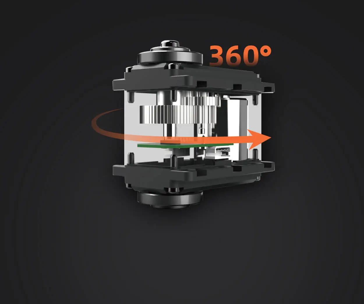
PWM サーボ ドライバー ボードは、パルス幅変調信号 (通常は 50 Hz で 1 ms ~ 2 ms) を受信し、それをサーボ上の対応する角度位置に変換します。単一のサーボの場合、ほぼすべての基本的なボードが機能します。しかし、実稼働環境では、ボードは複数のサーボを同時に管理し、チャネル間で一貫したタイミングを維持し、スパイク電圧や電流サージから保護する必要があります。
中心となる機能は信号分配と電力調整です。適切な信号調整がなければ、ハイエンドのサーボであっても予期しない動作をします。このボードはコントローラーと各モーターの間の仲介者として機能し、クロスチャンネル干渉なしにすべてのチャンネルが正しいパルス幅を受信できるようにします。
04実際のパフォーマンスを決定する主要な仕様
すべての PWM サーボ ドライバー ボードが同じ規格に基づいて構築されているわけではありません。オプションを評価するときは、次のパラメータに注目してください。
PWM周波数と分解能
標準的なサーボは 50 Hz で動作しますが、デジタル サーボは 200 Hz や 333 Hz などのより高い周波数でより優れたパフォーマンスを発揮することがよくあります。 50 Hz のみをサポートするボードでは、デジタル サーボで遅延が発生したり、解像度が低下したりする可能性があります。ビットまたはマイクロ秒で測定される分解能が高いほど、より詳細な位置制御が可能になります。
チャンネルごとの定格電流
サーボのサイズと負荷による連続電流引き込み。マイクロ サーボは 500 mA を消費する場合がありますが、工業用サーボは負荷がかかると 3 A 以上を消費することがあります。ボードは、電圧降下なしでピーク電流を処理できるようにする必要があります。ボードの電流供給が不足すると、サーボが停止したり、過熱したり、位置を失ったりします。
電圧範囲とレギュレーション
広い入力電圧範囲 (5 V ~ 8.4 V など) を備えたボードは、さまざまなサーボ タイプにわたって柔軟性を提供します。オンボード電圧調整機能は、サーボを過電圧状態から保護します。これは、バッテリまたは非安定化電源を使用する場合に重要です。
信号絶縁
In electrically noisy environments — near motors, inverters, or welding equipment — signal isolation prevents false triggers. Boards with optocouplers or dedicated isolation ICs are more reliable in industrial settings.
05 How Board Design Affects Heat, Jitter, and Signal Loss
Heat is the most common cause of premature driver board failure. When multiple servos draw current through a single board, the onboard voltage regulators and MOSFETs generate heat. If the board lacks a heat sink or proper copper pour design, temperatures rise quickly. Above 85°C, electrolytic capacitors degrade, solder joints weaken, and PWM signals become unstable.
Jitter — unwanted variation in pulse width — often results from poor clock source accuracy or insufficient decoupling capacitors. A board with a dedicated crystal oscillator and bypass capacitors on each channel produces cleaner signals. For applications requiring synchronized movement, such as robotic arms or camera gimbals, jitter tolerance is measured in microseconds.
Signal loss over long cable runs is another hidden issue. If your servos are located more than one meter from the board, voltage drop and signal attenuation become measurable. Boards with differential signal output or built-in cable compensation reduce this risk.
06 Multi-Axis Coordination: Why Channel Count Is Not Enough
Many buyers assume that more channels equal better capability. In reality, channel count matters only if the board can update all channels simultaneously at the required frame rate. Boards that use sequential update — updating one channel per cycle — introduce timing delays between servos. For applications requiring synchronized motion, such as walking robots or conveyor sorting systems, simultaneous update is essential.
Check whether the board uses a dedicated PWM controller IC (such as the PCA9685) or relies on software timing. Software-based boards are cheaper but introduce timing drift as the CPU load increases. Hardware-based boards maintain consistent timing regardless of how many servos are active.
07 Common Mistakes When Selecting a Driver Board
Mistake 1: Ignoring Power Supply Compatibility
A board rated for 6 V input cannot drive servos requiring 7.4 V. Always match the board's input range to your servo operating voltage.
Mistake 2: Overlooking Protection Features
Boards without reverse polarity protection, overcurrent protection, or thermal shutdown are risky in production environments. A single wiring error can destroy the board and connected servos.
Mistake 3: Assuming All Servos Use the Same Signal Standard
Some servos require inverted signals, extended pulse ranges, or different center points. Boards with configurable signal parameters reduce integration time.
Mistake 4: Choosing Based Only on Price
Low-cost boards often lack thermal management, signal filtering, and reliable connectors. The savings are quickly lost when field failures cause downtime.
08 Specifications Comparison Table
09 Questions Buyers Often Ask About PWM Servo Driver Boards
1. Can I use a 16-channel board for 12 servos running continuously?
Yes, but only if the total current draw does not exceed the board's power handling capacity. Verify the combined current at full load and compare it to the board's rated output.
2. What happens if the board's voltage is too low for my servos?
Servos will operate slower, with reduced torque, and may fail to reach commanded positions. Prolonged undervoltage can damage the servo motor windings.
3. How do I know if my board causes jitter?
If servos buzz, oscillate, or fail to hold position without external load, the board may be introducing signal jitter. Test with an oscilloscope to measure pulse width variation.
4. Do I need signal isolation for a factory automation setup?
In most factory environments with motors, drives, and welding equipment, signal isolation is recommended. It prevents electromagnetic interference from corrupting the PWM signal.
5. Can I drive analog and digital servos on the same board?
Yes, but analog servos are more sensitive to high-frequency PWM. If using a mixed setup, start with 50 Hz and verify performance before increasing frequency.
6. What is the maximum cable length between board and servo?
For standard PWM signals, keep cable length under 1.5 meters. Beyond that, use twisted-pair shielded cable or a board with differential output.
7. How often should I replace a PWM servo driver board in continuous use?
With proper thermal management, a mid-range or industrial board typically lasts 3–5 years. Entry-level boards may need replacement every 6–12 months under continuous load.
8. What is the most common failure mode of driver boards?
Overheating due to inadequate current handling or poor ventilation. The second most common failure is connector wear from repeated plugging cycles.
10アプリケーションに適したボードの選択
If you are building a single-axis test rig, an entry-level board may suffice. For multi-axis production systems, invest in a board with adjustable frequency, per-channel protection, and thermal management. The cost difference is often less than the value of one hour of unplanned downtime.
Start by listing your servo specifications — voltage, peak current, required frequency — then match those to a board that provides headroom of at least 20% on current and voltage. If your application requires synchronized movement across three or more axes, prioritize boards with hardware-based simultaneous update. For environments with electrical noise, signal isolation is not optional.
When comparing suppliers, ask for documentation on PWM accuracy, thermal testing, and connector reliability. A board that passes these checks will reduce maintenance frequency and improve motion consistency over the long term.
11 Need Help Selecting the Right PWM Servo Driver Board?
Choosing a driver board should not be a guessing game. If you are evaluating options for an upcoming project, send your servo specifications and motion requirements to the キロパワーサーボ engineering team. They can review your application parameters and recommend a board configuration that balances cost, performance, and reliability. A quick technical review upfront often prevents months of field troubleshooting.
Update Time:2026-07-12


