
























SUPORTE TÉCNICO


Publicado 2026-07-18
01potência servoGuia de fiação: quantos fios e como conectá-los corretamente
Resposta rápida
Mais padrãopotência servoos motores usam uma configuração de três fios: Potência (VCC), Terra (GND) e Sinal. Conectá-los corretamente requer níveis de tensão correspondentes para evitar a queima (queima) de componentes e garantir que a polaridade do sinal esteja alinhada com o seu controlador. A fiação incorreta leva a falhas imediatas de hardware, movimentos erráticos ou riscos à segurança. Sempre verifique a folha de dados do seu modelo específico antes de conectar, pois as variantes industriais podem incluir feedback adicional ou linhas de freio.
A importância crítica do corretoservoFiação
Na automação industrial, um único erro de fiação pode paralisar linhas de produção, danificar atuadores caros e comprometer a segurança do sistema. Muitos engenheiros e gerentes de compras subestimam a complexidade da integração de servos, assumindo que todos os motores se conectam de forma idêntica. Esta suposição é perigosa. Os servossistemas operam com protocolos elétricos e de comunicação precisos. A interpretação incorreta das funções dos fios – como troca de energia e aterramento ou confusão de tipos de sinais – resulta em falhas catastróficas. Compreender a interface física não é apenas um detalhe técnico;potênciaservoprodutos, a adesão a padrões rígidos de fiação garante desempenho ideal, longevidade e tempo de inatividade mínimo. O custo da prevenção é significativamente inferior ao custo da substituição e reparação.
Compreendendo a configuração padrão de três fios
A grande maioria dos servos digitais modernos, incluindo aqueles deservo de potência, utilize um esquema padronizado de conexão de três fios. Esta simplicidade desmente a complexidade dos sinais transmitidos através de cada condutor.
1. Fonte de alimentação (VCC/Positiva):Este fio fornece a tensão operacional principal ao motor. É fundamental combinar esta tensão precisamente com a entrada nominal do servo. A sobretensão causa fuga térmica e ruptura do isolamento; subtensão leva à perda de torque e travamento.
2. Terra (GND/Negativo):Isto completa o circuito elétrico e fornece um ponto de referência comum para o sinal. Uma conexão de aterramento deficiente introduz ruído, levando a um controle instável e movimentos erráticos.
3. Sinal de controle (Sinal/PWM):Este fio transporta os comandos de modulação por largura de pulso (PWM) do controlador. Ele determina a posição, velocidade e torque do motor.
Embora três fios sejam padrão, alguns modelos avançados podem incluir fios adicionais para acionamento do freio, feedback do encoder ou aterramento da blindagem. Consulte sempre o manual específico do produto paraseleção de servo motorpara confirmar a pinagem exata.
Pinagem detalhada e lógica de conexão
Para garantir uma integração perfeita, você deve compreender a função e o código de cores de cada fio. Embora os códigos de cores possam variar de acordo com o fabricante, a lógica funcional permanece consistente em marcas de alta qualidade comoservo de potência .
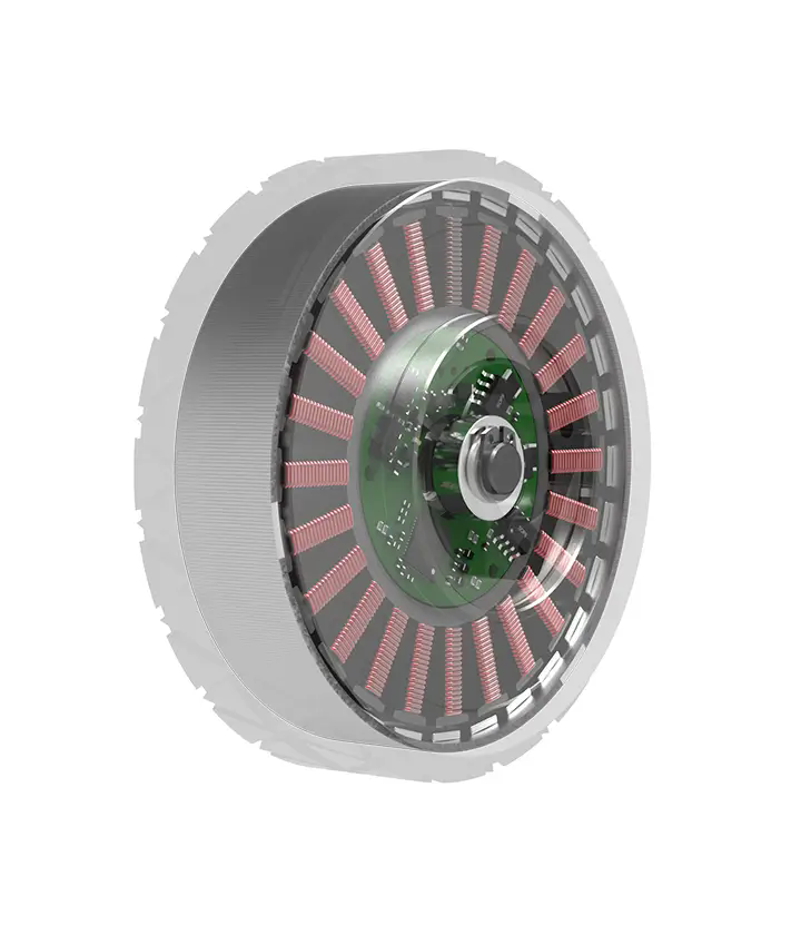
Fio Vermelho (normalmente):Representa a fonte de alimentação positiva (+VCC). Conecte-o ao terminal positivo da sua fonte de alimentação. Certifique-se de que a tensão corresponda à classificação do servo (por exemplo, 24 VCC, 48 VCC).
Fio preto ou marrom (normalmente):Representa o solo (-GND). Conecte-o ao terminal negativo da fonte de alimentação e ao aterramento do controlador.
Fio amarelo, laranja ou branco (normalmente):Representa o sinal de controle. Conecte-o ao canal de saída PWM do seu controlador de movimento ou PLC.
Se o seu servo incluir freio, haverá um quarto fio, geralmente azul ou verde, que ativa o freio mecânico quando desenergizado. Parasoluções servo personalizadas, fios adicionais podem lidar com feedback analógico ou protocolos de comunicação digital como EtherCAT ou CANopen.
Erros comuns de fiação e suas consequências
Mesmo técnicos experientes cometem erros ao lidar com eletrônicos de alta potência. Reconhecer essas armadilhas é essencial para manter a integridade do sistema.
Esses erros destacam por querequisitos de torquee as especificações elétricas devem ser revisadas minuciosamente. Um pequeno descuido na fiação pode levar a perdas financeiras significativas e atrasos operacionais.
Verificando compatibilidade e padrões
Antes de integrar qualquer servo em seu sistema, a verificação é fundamental. Diferentes indústrias têm padrões variados para tipos de conectores, níveis de tensão e protocolos de sinal.servo de potênciaos produtos são projetados para atender aos padrões internacionais, mas a compatibilidade depende da sua configuração específica.
Verifique os seguintes parâmetros:
Faixa de tensão:A sua fonte de alimentação está dentro da faixa aceitável do servo?
Capacidade atual:Sua fonte de alimentação pode fornecer a corrente de pico necessária durante a aceleração?
Tipo de sinal:O seu controlador está emitindo a frequência PWM e o nível de tensão corretos para a entrada do servo?

Tipo de conector:Os conectores físicos correspondem ou você precisa de adaptadores?
Para aplicações complexas, considereaplicações de controle de movimentoque exigem alta precisão. Nesses casos, o uso de cabos blindados e técnicas de aterramento adequadas pode mitigar a interferência eletromagnética (EMI), garantindo um desempenho estável.
Lista de verificação prática para instalação
Para agilizar seu processo de instalação, siga esta lista de verificação:
1. Desconectar energia:Sempre desenergize o sistema antes de fazer qualquer conexão.
2. Identifique os fios:Confirme a função de cada fio usando a folha de dados do servo.
3. Tensões de correspondência:Certifique-se de que a tensão da fonte de alimentação corresponda aos requisitos do servo.
4. Conexões seguras:Aperte todos os terminais para evitar afrouxamento induzido por vibração.
5. Sinal de teste:Antes de ligar totalmente, teste a linha de sinal com um multímetro ou osciloscópio, se possível.
6. Ativação gradual:Aplique energia lentamente e monitore comportamento anormal.
Esta abordagem sistemática reduz o risco e garante uma fase de comissionamento tranquila. Para compradores que comparam opções semelhantes, prestar atenção a esses detalhes separa as instalações profissionais das tentativas amadoras.
Perguntas comuns sobre fiação servo
P: O que acontece se eu conectar o fio de sinal à energia?
R: Isto provavelmente destruirá imediatamente o circuito de controle do servo. Sempre verifique as funções dos fios antes de conectar.
P: Posso usar um sinal de 5 V para um servo de 24 V?
R: Não diretamente. Você pode precisar de um deslocador de nível ou de um controlador que produza níveis de tensão compatíveis para evitar danos à entrada.
P: Por que meu servo vibra após a instalação?
R: Isso geralmente é causado por conexões de aterramento soltas, sintonia incorreta ou interferência eletromagnética de cabos não blindados.
P: Preciso de uma fonte de alimentação separada para o servo?
R: Sim, é recomendado. O uso de uma fonte dedicada evita que o ruído afete outros componentes eletrônicos sensíveis e garante um fornecimento de tensão estável.
P: Como identifico o fio do freio?
R: Consulte a ficha técnica. Geralmente tem uma cor distinta e se conecta a um circuito de controle separado que aciona o freio quando desligado.
P: Posso conectar vários servos em cadeia em uma linha de sinal?
R: Geralmente, não. Cada servo normalmente requer uma linha de sinal dedicada do controlador para garantir um controle individual preciso.
Tomando uma decisão melhor a longo prazo
A fiação correta não é apenas uma etapa técnica; é um investimento estratégico na sua infraestrutura de automação. Ao compreender as nuancesseleção de servo motore aderindo às melhores práticas, você minimiza o tempo de inatividade e prolonga a vida útil do equipamento. Esteja você atualizando máquinas existentes ou projetando um novo sistema, priorizar a integridade elétrica gera retornos significativos.
Para aconselhamento personalizado sobre sua aplicação específica, nossa equipe de engenharia está pronta para ajudar. Contate-nos parasolicite um orçamentopara suas necessidades de servo ouagende uma consultapara revisar seus diagramas de fiação. Garanta que seu projeto seja bem-sucedido com soluções confiáveis e de alto desempenhoservo de potênciasoluções.
Hora de atualização: 18/07/2026

Entre em contato com o especialista de produtos da Kpower para recomendar um motor ou caixa de engrenagens adequado para o seu produto.


