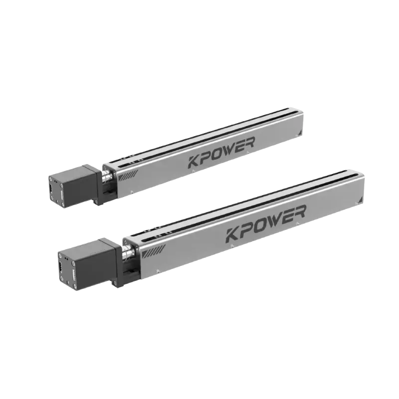
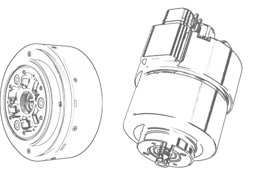
Kpower-KPCD

KPCD Protocol Overview
KPCD is the common serial communication protocol utilized across мощность products. Built on the standard CDBUS / CDNET serial protocol architecture, it supports multiple physical interfaces, including:
Dual-wire TTL
Single-wire TTL
RS-485
Hardware Controller & High-Speed Capabilities
Выбиратьмощность products feature an integrated CDBUS hardware controller, unlocking enhanced bus performance:
Active Slave Reporting: Slaves can proactively transmit data and respond to broadcast requests without master polling.
Collision-Free Transmission: Hardware arbitration automatically handles bus contention and schedules transmissions, eliminating packet collisions.
Ultra-High Speed: Supports communication throughput of up to 50 Mbps.
Baud Rate Switching & Recovery Window
Boot-Up Sequence: Upon power-on, мощность devices operate at a fixed default rate of 115,200 bps for a short initial window before automatically transitioning to the user-configured baud rate.
💡 Recovery Tip (Forgotten Baud Rate):
If the configured baud rate is lost or forgotten, you can regain control of the device by establishing a connection during this initial power-on window using 115,200 bpsиbroadcast address.
kpcd_protocol_v4
KPower Default Communication Protocol — KPCAN Protocol (CAN 2.0 / CAN FD)
⚠️ Prerequisites & Document Dependency:
This specification strictly depends on the KPCD Protocol Document. It must be used in conjunction with the KPCD document and cannot be used as a standalone reference.
1. Protocol Overview
KPCAN is the dedicated communication protocol utilized by KPower products over the CAN bus.
It is not an entirely new protocol from scratch; rather, it encapsulates and carries the KPCD serial protocol over CAN using the mapping rules detailed in this document:
Address Field Mapping: The address fields from the KPCD frame header are mapped into the 29-bit extended CAN ID.
Ports and Payload: The port identifiers, along with the accompanying data, are placed within the CAN Data Field (Note: In non-fragmented frames, the source port is also mapped directly into the CAN ID; see Chapter 2 for details).
Full KPCD Compatibility: All function port definitions, register maps, and related parameters are identical to KPCD. Please consult the KPCD Protocol Document for their detailed definitions.
2. Main Characteristics
Dual Standard Support: Fully compatible with both CAN 2.0иCAN FD.
Extended Frames Only: Exclusively uses 29-bit extended data frames; all remote frames on the bus are ignored.
Optional Fragmentation: Packets that exceed the maximum payload capacity of a single frame can be dynamically split across multiple consecutive frames.
3. Conventions Used in Examples
To maintain strict consistency with the KPCD documentation, all practical examples in this document adhere to the following default address configuration:
Master Address: 00 (0x00)
Device Address: fe (0xFE)
kpcan_protocol_v2
KPI2C Protocol Overview
KPI2C is the dedicated communication protocol utilized by KPower products over the шина I2C.
Similar to KPCAN, it is not an entirely new protocol from scratch; rather, it encapsulates and carries the KPCD serial protocol over I2C using the mapping rules detailed below:
Address Mapping: The destination address in the KPCD frame header is mapped directly into the I2C address byte.
Payload Transmission:LEN byte and all following data fields are transferred as-is without alteration (see Chapter 2 for detailed frame structures).
Full KPCD Compatibility: All function port definitions, register maps, and operational commands remain identical to KPCD. Please consult the KPCD Protocol Document for reference.
Bus Consistency:SPI bus adopts the identical frame format and mapping logic (refer to the KPSPI Protocol Document).
Main Characteristics of KPI2C
Strict Master/Slave Architecture:
A slave device never initiates a transfer spontaneously. All replies, status updates, and self-reported packets are queued in the internal buffer of the slave device until explicitly polled/read by the master.
Hardware-Defined Framing:
Transaction boundaries are strictly defined by standard I2C START / STOP conditions, eliminating the need for the serial bus-idle framing mechanism used in UART/RS-485.
Single-Master Topology:
Толькоone master is permitted on the bus at any time; multi-master arbitration mode is not supported.
Optional CRC Verification:
CRC calculation is optional and determined statically by firmware build macros at compile time.
Addressing & Register Conventions
| Address Width | 6 bits | Valid device address range: 0x00 ~ 0x3E |
| Broadcast Address | 3f (0x3F) | Broadcasts commands to all connected slaves |
| Default Example Address | 3e (0x3E) | Target device address used across document examples |
| Master Source Port | 40 (0x40) | Default host/master source port used in examples |
⚠️ Note on Serial-Specific Registers:
All serial-related registers defined in the base KPCD document (such as baud_rate, bus_idle_wait_len, bus_tx_permit_len, etc.) have no meaning and are invalid under the I2C interface.
kpi2c_protocol_v1