


TECHNICAL SUPPORT


Published 2026-02-16
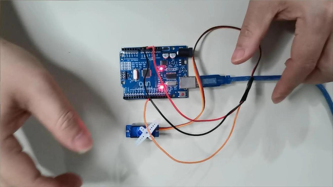
I just got theservoand wanted to connect it to the microcontroller, but I was confused looking at the three wires? Don't worry, this is a problem that almost every newbie who playsservos will encounter. In fact, wiring is simpler than you think. As long as you understand what the three wires are for, and follow the steps step by step, you can be sure to get theservomoving within half an hour.
The three wires extending out of the servo are usually the power wire, ground wire and signal wire. The power wire is usually red and is connected to the 5V pin of the microcontroller to power the servo. The ground wire is brown or black and is connected to the GND pin of the microcontroller to allow the circuit to form a loop. The signal line is usually orange or yellow, which is connected to the PWM output pin of the microcontroller, and is used to control the rotation angle of the servo. Understanding the functions corresponding to colors is a solid first step.
If you have connected according to the color, but the servo does not move, the most common reason is insufficient power supply. The 5V pin current of the microcontroller itself is limited, and it cannot drive the big eater of the servo. In this case, the servo may vibrate slightly but not turn, or may not respond at all. Try connecting a separate external power supply to the servo, such as a battery pack or voltage stabilizing module, and connect the ground wire of the power supply to the ground wire of the microcontroller. The signal line remains unchanged, and the problem can usually be solved.
The choice of power supply depends on what kind of servo you are using. If it is an ordinary small torque servo, the working current is several hundred milliamps, and it can be driven by modifying it with a few dry batteries or a mobile phone power bank. If it is a high-torque metal servo, the operating current may reach several amps, so you have to consider using a special model aircraft battery or a high-power voltage stabilizing module. The key is to look at the nominal working voltage and locked-rotor current of the servo. According to this parameter, add a 20% margin to make it practical to use.
After the wiring is done, it's time to write the code. You need to output a PWM wave to the pin where the signal line of the microcontroller is located, which is the control signal needed to simulate the servo. Generally, the steering gear requires a frequency of 50Hz, which means a cycle of 20 milliseconds. In this cycle, the high level time is between 0.5 milliseconds and 2.5 milliseconds, corresponding to 0 degrees to 180 degrees of the servo. There are ready-made Servo libraries in the library functions of many microcontrollers. You can directly call the writing angle without having to calculate these complicated times yourself.
If you want the robot to move, one servo is definitely not enough. When wiring multiple servos, power supply becomes a big problem. At this time, don't think about using the power supply of the microcontroller. You must use an external power supply, and the power supply must be large enough. Connect the red wires of all servos together to the positive pole of the power supply, and the black wires together to connect the negative pole of the power supply and the common ground of the microcontroller. The signal lines are respectively connected to different PWM pins of the microcontroller. In this way, each servo can be controlled independently in the program and let them work together.
Sometimes the angle is written, but the position of the servo is always deviated. This may be due to interference in the signal line, especially when the wiring is relatively long. Try twisting the signal wire and the power ground wire together, which can play a certain anti-interference effect. In addition, the potentiometer inside the servo also has physical errors. You can slightly adjust the pulse width range in the code and fine-tune it to make the angle more accurate. If it is not accurate after long-term use, it may be that the servo itself is worn and needs to be replaced.
Burning something is usually caused by too much current or wrong wiring. Be sure to double-check the power supply voltage before wiring. Never connect the high-voltage power supply directly to the servo. The negative pole of the external power supply that supplies power to the servo must be connected to the GND of the microcontroller, so that a unified reference level can be formed. When debugging the program, you can first place the servo at a middle angle before powering on to prevent the servo from suddenly turning to the bottom and causing excessive current at the moment of powering on. If you feel that the servo is hot or making abnormal noises, immediately cut off the power and check.
I hope these contents can help you successfully take the first step in steering servo control. Think about it, what is the specific problem that troubles you the most when you are wiring or programming? Welcome to chat about your experience in the comment area. If you find it useful, don’t forget to give it a like and share it with more friends who need it.
Update Time:2026-02-16
Contact Kpower's product specialist to recommend suitable motor or gearbox for your product.


