


TECHNICAL SUPPORT


Published 2026-02-13
What's the most troublesome thing about steering gear? It's not that I can't afford it, or that I can't write the program, but I have three wires in my hand and I don't know where to plug them in. If you insert it wrongly, you will get smoke, but if you insert it correctly, you will get lucky. There are a lot of pictures on the Internet, but they are either too professional or look like a blur. Today we will break down the wiring of theservoat once and explain it clearly in a way that you can get started immediately.
The three wires extending out of theservoare basically in three colors: brown, red, and orange. There are also black, red, and white ones, and the principle is the same. Brown or black is the negative pole, connected to GND; red is the positive pole of the power supply, connected to 5V; orange or white is the signal line, connected to the control pin. This color scheme is common to 95% of servos. If you can't remember it, you only need to remember the order of "brown, red and orange", just like the traffic lights in reverse, it will never be confusing.
Where do many novices fall? It's not that I don't know the definition, it's just that I didn't align it correctly when I inserted it. For example, the spacing between the pins and the servo plug completely match, but if you push it to the middle of the breadboard, the pins are crooked, and the signal wire is plugged into the power hole. At this time, the servo either doesn't respond or shakes like an electric shock. In fact, it's not a program problem at all, but the lines are misaligned.
This is the most asked question, and the answer is not necessarily, but it is possible. There is a drive board inside the servo. If you just reverse the positive and negative poles, the servo will make a "click" sound when the power is turned on, and then it will not respond. At this time, cut off the power immediately, and the line will usually still work if it is adjusted back. But if you connect it reversely for a long time, or use a power supply with a high power, the voltage stabilizing chip on the driver board may burn out.
The most concealed reverse connection is the wrong plugging of the signal cable. Some people plug the signal line into the power supply, and the servo can actually move, because the high level pours into the control circuit through the IO port. It can be used for a short time, but the pins will get hot. Over time, either the servo or the main control will be broken. Therefore, develop a good habit before plugging in the wire: take a look at the color, confirm the position of the three pins, and then do it.
There is a pain point in connecting the servo to the breadboard: the servo plug is a DuPont female connector, and the breadboard hole is round, so it is loose when plugged in, and the contact will break if you move it a little. At this time, don't force it or wrap it with tape. The best solution is to use a breadboard-specific jumper as a relay. You plug the servo cable into one end of the jumper and the other end of the jumper into the breadboard. The contact area is large and the signal is much more stable.
If you're working on a mobile project, such as a robot car, a breadboard won't be able to withstand bumps. A more reliable method is to solder the servo wire directly to the adapter board, or use hot melt glue to stick the plug to the edge of the breadboard. Some people think this is difficult to disassemble. In fact, during the debugging stage, use a breadboard and add jumpers, and solder them directly after finalization. This is the normal process of research and development.
Many people think that all digital pins can directly drive the servo, but this is not the case. The signal of the servo is very sensitive to the pulse width, and the output PWM frequency is 980Hz or 490Hz. The servo requires 50Hz, which is a 20 millisecond period. If you send a signal to the servo, it will either not turn in place or vibrate crazily.
The correct way is to use the Servo.h library, which will automatically switch the pin to 50Hz mode. What's more important to note is that the Servo library only supports specific pins by default, such as 9 and 10 on Uno, and much more on Mega. If you find that the servo does not work when connected to a certain pin, try changing it to 9 or 10, and 80% of the time the problem can be solved. This is not metaphysics, it is the timer channel that is programmed into the bottom layer of the library.
When a high-torque servo is used in a project, it is not possible to draw power directly from the 5V pin. When the rotor is blocked, the current can reach 2A, and the USB port is directly protected, and the board cannot withstand it. The correct approach is to divide the power supply into two channels: one for the main control board and one for the servo alone. The GNDs of these two channels must be connected together, otherwise the signal will have no reference level.
Many finished servo driver boards will integrate power supply and signal, for example, there will be separate power terminals on the board. If you build the circuit yourself, the easiest way is to use a breadboard power module, input 7-12V, output 5V to the servo, and short-circuit the GND of the module and the GND of the module. In this way, if the main control dies, the servos will still turn without interfering with each other.
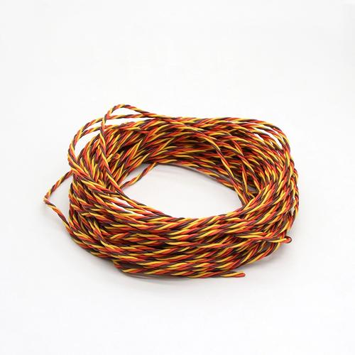
When making a bionic robot or robotic arm, the servo is far away from the main control board and requires an extension cable. Dupont cables on the market, which cost only a few cents each, can be plugged into each other and turn on the lights, but there are often problems transmitting the servo signals. The reason is that the servo signal is a square wave with a period of 20ms. If the wire is too long or the wire core is too thin, the edges of the waveform become rounded, and the main control cannot recognize the pulse width.
The safe way is to buy silicone wire and crimp the terminals yourself. Choose a wire gauge of 24AWG or above, and control the length within 30 cm. If it must be more than 50 cm, add a 100 ohm resistor between the signal line and GND, or add a small capacitor at the servo end to filter out noise. Another finished product is a servo extension cable with a magnetic ring, which is very useful for suppressing high-frequency interference, especially when the servo cable and motor power cable are tied together.
After reading this, do you also want to try to reconnect the jumping servo on your hand? What's the weirdest wiring glitch you've ever encountered? Come to the comment area to talk about it. Maybe the pit you have stepped on is someone else’s life-saving straw tonight. If you find it useful, remember to like and forward it. Next time you write a guide to avoid pitfalls in steering gear programs, you will be able to see it immediately.
Update Time:2026-02-13
Contact Kpower's product specialist to recommend suitable motor or gearbox for your product.


