


TECHNICAL SUPPORT


Published 2026-03-30
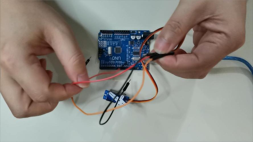
Have you ever encountered this situation: you were full of joy when you got a newservoand were about to start debugging it, but when you looked at those colorful wires, you suddenly became confused? Which wire is connected to the power supply and which wire is the signal wire? Don't worry, today we will talk about theservocables.
The most common servos on the market actually have two wire numbers. One is the 3-wire version, which is the most mainstream "standard version". The other type is 5-wire, usually seen on "robot-specific" or "continuous rotation" servos. Why is there this difference? To put it simply, the 3-wire servo integrates the power supply, ground wire and control signal, making it a "plug and play" fool-proof design. As for the 5-wire servo, the extra two wires are usually used to provide "feedback signals", which can tell your controller "where am I turning now", so that your robot can know where its joints are, achieving more precise control.
The wiring of 3-wire servos can be said to be the first lesson for all enthusiasts. These three wires have a very clear division of labor: the red wire is the "positive pole", usually connected to a 5V or 6V power supply; the brown or black wire is the "negative pole", which is the ground wire; the remaining orange or yellow wire is the "signal wire", used to receive instructions from the controller. You only need to connect the three red, brown and orange wires to your STM32 or servo control board respectively. Here is an experience that will help you avoid detours: After connecting the wires, remember to gently move the output shaft of the servo with your hand. If you feel little resistance, congratulations, the wiring is correct. If it feels stuck, it's probably because the power cord and ground wire are connected incorrectly. Turn off the power and check immediately.
If your servo has 5 wires, it probably has some "high-end" attributes. In addition to the power, ground and signal wires mentioned above, the two extra wires are usually "position feedback wires", some are two white wires, some are two thin wires. These two wires are directly connected to the potentiometer inside the servo, which will send the current angle value of the servo in the form of a voltage signal in real time. This is a great tool for projects such as robotic arms and bipedal robots that require precise control of angles. You can read this feedback value to perform a closed-loop control, such as letting a robotic arm grab a cup. When it senses resistance (increased current) or the angle is not in place, it can automatically adjust the strength to prevent the cup from being crushed.
This question is something almost every newbie worries about. To tell you the truth, it is right to have this worry. Many cheap servos, if the positive and negative poles of the power supply are connected reversely, will smoke and burn instantly, and the driver chip inside will die directly. However, many brands of servos or slightly better servos now have internal anti-reverse protection. Even if it is connected backwards, it just doesn't work and won't burn out. However, we cannot place our hopes on "maybe it won't burn". The safest way is to develop a good habit of measuring the output end of the power supply with a multimeter before wiring to confirm the voltage and polarity. Or connect a 1-2A fuse in series to the power input end. In this way, even if the connection is reversed, it will only burn the fuse. It only costs a few cents to replace it with a new one. It is always more cost-effective than replacing a servo that costs tens or hundreds of dollars.
This depends on your specific needs. If you are just starting to play, or just want to make a simple robotic arm, car, or gimbal camera, then just choose a 3-wire standard servo. The wiring is simple and the program is easy to write. There are a lot of examples online. But if you are working on a project that requires "product innovation", for example, you want your robot to have adaptive grabbing capabilities, or you need to monitor the working status of the servo in real time, then the 5-wire servo is your best choice. It can add a "feeling" dimension to your project, letting you know whether the steering gear is implemented properly. Of course, choosing a 5-wire servo means that your controller needs several more analog inputs to read feedback signals, which will also make your hardware circuit a little more complicated, but for the realization of the function, this complexity is worth it.
When you are ready to use a servo on your innovative product, it is not enough to know just a few wires. You also need detailed parameters such as "gear material", "core motor or core motor", and "waterproof level". At this time, the most reliable way is to search the official website of the company for this steering gear brand. For example, if you directly search for "XX steering gear official website", you can usually find the corresponding specifications in the product center (). In the specification book, not only will the color and definition of each wire be marked in detail, but it will also tell you its stalled current, no-load current, working dead zone, etc. These are indispensable data when you design the circuit and write the program. In addition, many manufacturers will also have "Technical Information Download" and "FAQ" columns on their official websites. These places often contain valuable experiences summed up by experienced engineers after going through pitfalls. It is worth spending time to study.
When you start working on your next project, will you give priority to 3-wire servos to simplify development, or 5-wire servos to obtain more precise feedback control? Share your thoughts in the comment section.
Update Time:2026-03-30
Contact Kpower's product specialist to recommend suitable motor or gearbox for your product.


