


TECHNICAL SUPPORT


Published 2026-04-13
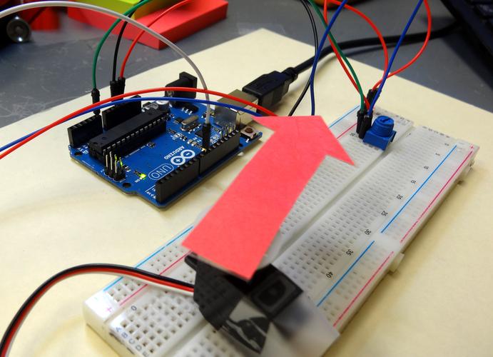
This guide explains the working principle of a standard radio-controlled (RC)servoused in model aircraft. By understanding the internal components and signal processing, you will be able to diagnose common issues, select the rightservofor your plane, and optimize control surface movements for safer flights.
An RC servo is a compact electromechanical device that converts a control signal from the receiver into precise angular movement of a control surface (e.g., aileron, elevator, rudder). In a typical foam trainer plane, the servo rotates the aileron pushrod by 45° when the transmitter stick is moved halfway – this changes the wing’s lift and banks the aircraft.
Core function:Transform electrical pulses into mechanical position with enough torque to overcome air pressure on the control surface.
Every standard analog servo contains three key parts working together:
The receiver sends a Pulse Width Modulation (PWM) signal. The servo reads the width of the positive pulse (usually between 1ms and 2ms) repeated every 20ms (50Hz).
1.0 ms pulse→ shaft rotates fully counter‑clockwise (e.g., -45°)
1.5 ms pulse→ shaft centers at 0° (neutral position)
2.0 ms pulse→ shaft rotates fully clockwise (e.g., +45°)
Common case:When your transmitter stick is released,it outputs a 1.5ms pulse. The servo returns to neutral, and the aileron becomes flush with the wing.
Let’s walk through what happens when you move the stick from center to full right:
1. Signal decoding– The servo’s control IC measures the incoming pulse width (now 2.0ms).
2. Position comparison– The IC reads the potentiometer’s current voltage (representing the shaft at 0°).
3. Error calculation– Difference = 2.0ms – 1.5ms = 0.5ms error → requires +45° rotation.
4. Motor drive– The H‑bridge drives the DC motor forward.
5. Gear reduction– The motor spins at high speed; the gear train reduces rpm to ~60 rpm at the output shaft.
6. Feedback loop– The potentiometer voltage changes as the shaft turns. Once it reaches the voltage corresponding to 2.0ms (full right), the IC cuts motor power.
The entire process takes 0.1–0.2 seconds for a standard analog servo. Digital servos use higher frequency pulses (up to 300Hz) for faster response.
Imagine your model’s rudder servo stops centering. You move the stick to neutral, but the rudder stays 10° off. This happens when the potentiometer’s internal wiper wears out or gets dirty. Without accurate voltage feedback, the servo cannot find the 1.5ms neutral position.
Solution:Replace the servo. Never attempt to repair the potentiometer – it’s sealed and calibration will drift.
Use this decision table based on real‑world flying conditions:
Key metric:Stall torque at 4.8V or 6.0V. Always use the voltage your receiver provides.
Secure mounting– Use rubber grommets and brass eyelets to absorb vibration. A loose servo causes flutter.
Correct horn orientation– Center the servo with a 1.5ms pulse, then attach the horn at 90° to the pushrod.
Limit end points– Adjust transmitter EPA (End Point Adjustment) so the control surface doesn’t bind at full throw. Binding overloads the servo and drains your battery.
Test with no load– Disconnect the pushrod, move the stick. The servo should rotate smoothly without buzzing. Buzzing means the potentiometer is not matching the signal – recalibrate or replace.
1. Pulse width determines position– 1.0ms (left), 1.5ms (center), 2.0ms (right).
2. Closed‑loop feedback– The potentiometer constantly tells the IC where the shaft is; the motor runs until position = command.
3. Torque multiplication– The gear train trades speed for force, enabling a small motor to move large control surfaces.
For beginners– Start with nylon‑geared analog servos (e.g., 9g micro servos). They are cheap, and you can learn centering and horn installation without risk.
For advanced flyers– Use digital, metal‑geared servos on all critical surfaces (elevator, rudder). Program fail‑safe so the servo moves to a predefined position (e.g., slight up elevator) if signal is lost.
Before each flying session– Perform a servo test: move each stick slowly and listen for grinding, hesitation, or buzzing. Replace any servo that does not return precisely to the same neutral position three times in a row.
Storage– Never store the aircraft with the servo under load (e.g., control surface deflected). Return all sticks to neutral before powering off.
By mastering how a servo reads PWM, compares position, and drives its motor, you will diagnose issues in minutes and choose the right components for any model aircraft. Always remember: a properly functioning servo is the difference between a controlled landing and a crash.
Update Time:2026-04-13
Contact Kpower's product specialist to recommend suitable motor or gearbox for your product.


