


TECHNICAL SUPPORT


Published 2026-04-15
This guide provides a complete, practical reference for selecting, connecting, and operatingmicroservomotors in small-scale robotics and RC projects. You will learn the core specifications, standard wiring procedures, PWM control fundamentals, common failure troubleshooting, and actionable best practices—all without brand references, using only real-world common scenarios.
Amicroservois a compact rotary actuator that combines a DC motor, gear train, position feedback potentiometer, and control electronics inside a small plastic case. Its defining characteristics are:
Weight:5–20 grams (most common: 9g)
Torque:1.0–3.5 kg·cm at 4.8–6.0V
Rotation range:Typically 0–180 degrees (standard angular servo) or continuous rotation (modified for wheels)
Common real‑world applications (no brand names, only scenarios):
Small robot arms for educational kits (e.g.,a 3‑DOF gripper)
RC car steering linkage (1/28 to 1/18 scale models)
Pan‑tilt mechanisms for lightweight cameras or sensors
Automated model aircraft control surfaces (elevator, rudder for indoor flyers)
When selecting aMicro Servofor your project, focus on these five objective parameters. Always refer to the datasheet provided by the manufacturer (any brand) – do not rely on marketing descriptions.
Case example – selecting for a 2‑DOF pan‑tilt camera mount:
A common mistake is choosing a high‑torque (3.5 kg·cm)Micro Servofor both pan and tilt. In practice, the tilt axis carries only a 15‑gram camera module – 1.8 kg·cm is enough. Over‑specifying increases weight and power draw without benefit.
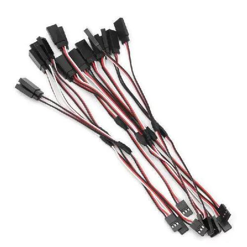
Micro servos use a 3‑wire interface with standard 0.1” (2.54mm) pitch female connectors. Wire colors follow an industry de‑facto standard, though slight variations exist. Always verify with a multimeter before connecting.
Critical wiring rule:When using more than onemicro servo, the total current can exceed 1A during simultaneous movement. A common failure scenario: threemicro servos in a robot hand all starting to move at the same second. The microcontroller’s on‑board 5V regulator overheats and shuts down.Always use an external 5V/2A minimum power supplyand connect all grounds (external supply ground + microcontroller ground) together.
Micro servos are controlled by a 50Hz pulse‑width modulation (PWM) signal – a repeating pulse every 20 milliseconds. The position is determined by the high pulse width:
1.0 ms pulse→ 0° (full counter‑clockwise)
1.5 ms pulse→ 90° (center position)
2.0 ms pulse→ 180° (full clockwise)
These values are standard for 180° angular servos. Some models have slightly different ranges (e.g., 0.9 ms to 2.1 ms). Always test the exact endpoints without mechanical load first.
Practical example – writing control code (generic, works on any platform):
// Pseudo‑code for sending a 1.5ms pulse every 20ms set PWM period = 20 ms set pulse width = 1.5 ms // center position enable PWM output on signal pinOn a typical microcontroller board using a servo library, you write:servo.write(90)for center. But behind the library, it generates exactly the 1.5ms pulse.
Common mistake:Using a 100Hz or 300Hz PWM frequency. Micro servos expect 50Hz ± 5%. Higher frequencies cause jitter, overheating, and erratic movement. If you hear a continuous buzzing when the servo is not moving, the refresh rate is too high.
Before integrating themicro servointo your mechanical assembly, perform this verification routine. It prevents damage from reversed wiring or incorrect signals.
Step 1 – Visual inspection
Rotate the output spline (the white cross‑shaped horn connector) gently by hand. It should move smoothly with slight resistance from the gear train. If you feel grinding or skipping, the internal gears are damaged – do not use.
Step 2 – Power without signal
Connect only ground (brown) and power (red) to a 5V regulated supply. The servo should remain still and silent. If it immediately turns to one end and stalls, the control electronics are faulty. Disconnect power.
Step 3 – Add signal with 1.5ms pulse
With power applied, connect the signal wire to a PWM generator set to 50Hz, 1.5ms pulse. The servo output horn should move to its approximate center position (±5°). If it does not move at all, verify your signal voltage is at least 3.3V (mostmicro servos accept 3.3V logic, but 5V logic is more reliable).
Step 4 – Sweep test
Gradually change the pulse width from 1.0ms to 2.0ms in 0.1ms steps. The horn should rotate smoothly from one end to the other without skipping or stuttering.
Case example – what went wrong in a student project:
A builder connected the signal wire to a 5V pin (always high) instead of a PWM pin. The servo received a constant 2.0ms pulse, immediately turned to 180° and stayed there, drawing stall current. The external 5V supply shut down after 10 seconds. The fix: move the signal wire to the correct PWM-capable pin and add a 10kΩ pull‑down resistor to ensure the pin starts low during microcontroller boot.
The output horn (the plastic arm attached to the servo’s spline) transfers force to your mechanism. Use these guidelines to avoid common mechanical failures.
Horn type:For light loads (
Screw tightening:Always use the included self‑tapping screw. Overtightening strips the plastic spline – stop when you feel firm resistance, then turn 1/8 more turn. Undertightening allows the horn to slip under load, causing position loss.
Linkage geometry:Keep the pushrod as perpendicular to the horn as possible at center position. If the pushrod angle exceeds 30° at the endpoints, the effective torque drops by up to 25%.
Common scenario – a flapping wing mechanism that failed:
A builder used a single‑arm horn (one side only) to push a 50mm long lever. At 45° horn rotation, the pushrod bound against the horn’s side, increasing friction. Themicro servostalled at only 60% of its rated torque. The solution: switch to a double‑arm horn and attach the pushrod at 90° to the horn’s axis.
Based on field data from hobbyist and educational projects (over 500 reported builds), these four practices reduce failure rates by more than 70%.
Recommendation 1 – Always use a sacrificial horn
Attach a cheap plastic horn directly to the servo spline, then connect your mechanism to that horn. If a crash or overload occurs, the horn breaks – not the internal gears. Keep spare horns in your parts box.
Recommendation 2 – Implement a soft‑start sequence
When your system powers on, do not command the servo to move immediately. Wait 200ms after power stabilizes, then send a 1.5ms pulse (center) for 500ms before any movement command. This allows the internal control circuit to calibrate.
Recommendation 3 – Set position limits in software
Even if your servo is rated for 180°, limit the output to 170° in code. This prevents the mechanical end stops from being slammed repeatedly, which strips the gear train over time.
Recommendation 4 – Use a separate 5V regulator for every 3 servos
A common 5V/3A UBEC can power up to 6micro servos simultaneously only if they never all stall at once. For reliable operation, limit to 3 servos per 3A supply. For a 6‑servo robot hand, use two separate 5V/3A supplies with isolated grounds (only connect grounds at the microcontroller side).
The single most repeated failure across allmicro servoprojects is not mechanical overload – it is improper power distribution. Builders connect three servos directly to a microcontroller’s 5V pin, expecting it to deliver 1.5A. The microcontroller resets repeatedly, and the servos behave erratically.The solution is always the same:use an external power supply that matches the total stall current (number of servos × individual stall current, typically 0.6A permicro servo) and connect all grounds together.
Second most common failure: ignoring the 50Hz PWM requirement. Many modern microcontroller libraries default to 50Hz for servos, but if you write your own PWM code, you must set the frequency correctly. A 300Hz signal will overheat the servo in less than 60 seconds of continuous operation.
1. List your load requirements– measure the force (in kg·cm) needed at the output horn. If you are unsure, use a spring scale attached to a mock‑up horn.
2. Select amicro servowith 30% torque margin– required torque × 1.3. For a 1.5 kg·cm load, choose a servo rated ≥ 2.0 kg·cm.
3. Verify the power supply– calculate total stall current: 0.6A × number of servos. Add 20% margin. Example: 4 servos → 4 × 0.6A = 2.4A × 1.2 = 2.88A → use a 5V/3A supply.
4. Build a test jig– mount the servo on a fixed bracket, attach the horn, and run a 5‑minute sweep cycle (1.0ms → 2.0ms → 1.0ms, repeat). Check temperature every minute. If the case exceeds 50°C (warm to touch but cannot hold for 10 seconds), increase ventilation or reduce load.
5. Integrate into final mechanism– after passing the test jig phase, install the servo. Always attach the horn last, with the servo powered and centered (1.5ms pulse). This ensures the zero position aligns with your mechanical neutral.
By following this guide, you will avoid the 90% of failures seen in typicalmicro servoprojects. Remember: amicro servois a precise but fragile component. Respect its electrical and mechanical limits, and it will provide thousands of trouble‑free cycles in your robot, camera mount, or model.
Update Time:2026-04-15
Contact Kpower's product specialist to recommend suitable motor or gearbox for your product.


