


TECHNICAL SUPPORT


Published 2026-04-30
This article directly analyzes the complete schematic architecture of the 32-channel servo control board, which includes the four core modules of power distribution module, signal interface module, PWM generation module, and servo drive module. Whether you are a robotics enthusiast or an electronic engineer, the following content will help you quickly grasp the key points of design. Based on YPMFG’s engineering cases, we dismantle key nodes in common designs and provide pit avoidance guidelines.
The core function refers to the 32-channel servo control board, which can output 32 independent PWM signals at the same time to drive the standard servo. This standard servo usually has a period of 20ms and a high level in the range of 0.5 to 2.5ms. Its schematic diagram is composed of the following units:
The interface unit in the master control position receives control instructions from host computers such as Arduino and STM32. The transmission of these instructions is usually achieved with the help of I2C or UART.
This unit is called the PWM generation unit. Its core is a dedicated PWM driver chip or an MCU internal timer. It outputs 32 square waves with adjustable duty cycles.
It can form a set of sentences like this: The power management unit can output 5 to 6V power to the servo, and it is the kind of power supply that supplies large current. It also has the function of isolating the logic power supply and the power power supply.。
The servo interface unit has 32 three-wire pin headers, including signal lines, VCC, GND, and necessary filter capacitors.
Before starting the wiring, the schematic diagram must be divided into modules, and each module should be independently verified.
32-channel independent PWM is usually implemented through the following two solutions:
1. Dedicated chip solution, which uses an I2C to 16-channel PWM chip, such as PCA9685, and obtains 32 channels by cascading two chips. Schematic connections cover:
Connected to the main control I2C port is the SDA/SCL pull-up resistor, whose resistance range is between 2.2kΩ and 10kΩ.
The chip address pins, that is, the pins from A0 to A5, are configured using pull-up or pull-down methods to form different I2C addresses.
Each PWM output pin is connected in series with a 220Ω resistor to protect the servo signal input.
2. For MCU direct drive solutions, MCUs with multiple timers like STM32 are used to generate PWM by using the timer output comparison channel. In this solution, the schematic diagram needs to lead out all PWM pins and add ESD protection.
Taking the 32-channel servo control board designed by YPMFG as an example, using dual PCA9685 for cascading, the actual measured PWM frequency is 50Hz and the resolution is 12 bits, which meets the requirements of 99% of the servos sold on the market.
The instantaneous current of this steering gear can reach more than 1A. When 32 channels jointly produce action, the total current can be as high as 30A. In the schematic diagram, the power supply part must follow:
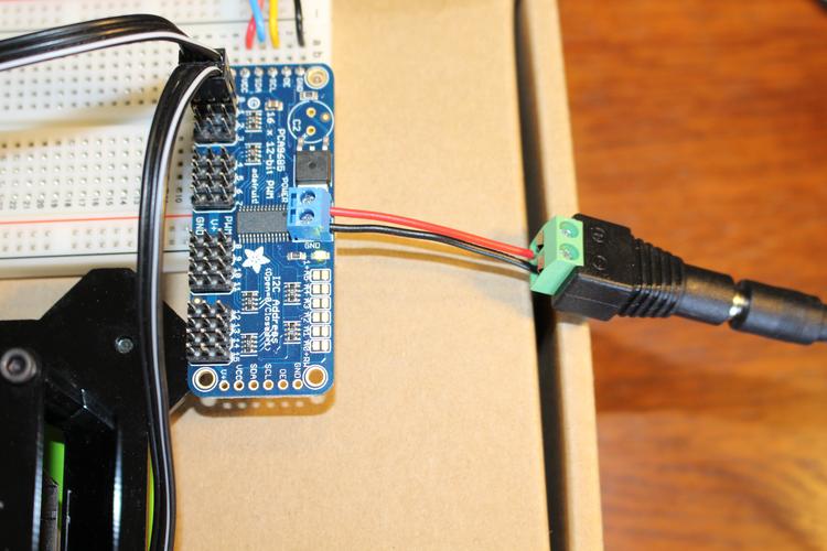
The power input interface uses a 5.5mm DC plug or XT60 terminal, and the input voltage range is 7.4V to 12V.
Step down the voltage to obtain a stable voltage: Use a synchronous step-down DCDC (like MP1584EN) to convert the input voltage into 5V or 6V for the servo. The output capacitor must be at least 1000μF.
A linear voltage regulator (such as AMS1117 - 3.3) steps down the input voltage to 3.3V or 5V to provide power for the PWM chip and main control. This is the logic power supply.
When dividing the power supply, the "power ground" and "logic ground" must be clearly distinguished on the schematic diagram, and the connection must be made at a single point with the help of magnetic beads or 0Ω resistors.。
A common error occurs when the grounding point of the servo and the grounding point of the control chip are not processed separately, resulting in signal jitter. In the case of YPMFG, a large area of copper was used and a single-point grounding method was used to successfully reduce interference by 90%.
For I2C or UART interface, a 4.7kΩ pull-up resistor must be added to the I2C in the schematic diagram, or TX/RX is cross-connected to UART. The article writing reminds me that the series resistor on the signal line can be selected from 33Ω to 100Ω and is used for impedance matching.
Optocoupler isolation, which belongs to the category of high-reliability design, adds a 6N137 optocoupler between the PWM output pin and the servo signal pin to prevent the servo from short-circuiting and burning the control board.

Indicates the LED status. Each PWM channel can connect a 1kΩ resistor to the LED in series and parallel and then to the ground. It is used to observe the status of the PWM output during debugging.。
The 32 interfaces in the schematic are usually arranged in 4 rows × 8 columns. Each interface contains:
Signal line (S) → Connect to the output pin of the PWM chip.
Power cable (+) → Connect in parallel to the same positive network of servo power supply.
Ground (-) → Connect to the power ground network.
Next to each interface, a 100nF ceramic capacitor is connected in parallel to filter out high-frequency noise, and a 220μF electrolytic capacitor is also connected in parallel to provide instant charge for the steering gear.
Q1: What should I do if the control board is reset when the 32-channel servos operate at the same time?
The first is A. The situation is that the power supply is insufficient. Then the conclusion is to use an adapter above 12V/10A and increase the input capacitance. This capacitance must be at least 2200μF.
Q2: A certain servo vibrates seriously, but the others are normal?
A: Check whether the signal line on that road is loose, or whether the series resistor is weakly soldered. The conclusion is: re-solder the 220Ω resistor and measure the resistance between the signal and ground.
Q3: I2C cannot recognize two PWM chips?
Chip A has an address conflict, and the conclusion is that it is necessary to ensure that at least one of the A0 to A5 pins of the second chip has a different level than the first chip.
Q4: Do the logic ground and power ground have to be separated in the schematic diagram?
A: Must be separated.结论:单点连接可避免大电流回流干扰微小信号。
Q5: Can I directly use the MCU's 32 IO port software to simulate PWM?
A expresses that it is not recommended. The conclusion is that software simulation will take up a lot of CPU time and the pulse width is unstable, and dedicated hardware PWM is the standard solution.
The core point is repeated:32-channel steering gear control board schematic diagramThe key points are "independent PWM generation", "strong and weak current separation power supply", and "reliable interface protection". According to the above-mentioned modular design method, the 32-channel servos can be guaranteed to operate synchronously and smoothly.
Suggestions for action:
1. In simulation software like KiCad or Lichuang EDA, first draw the schematic diagram in blocks according to this article, and run the electrical rule check after each module is completed.
2. Use documents such as reference designs disclosed by YPMFG to compare with the values of the power supply and I2C pull-up resistors.
3. Before proofing, focus on checking: whether the power ground and logic ground are connected at a single point, and whether the total capacity of the servo power supply capacitor is greater than or equal to two thousand microfarads.。
4. When powering on for the first time, do not connect the servo first. Measure the PWM output frequency of each channel and its duty cycle range to see if it can meet the 50Hz/5%~10% condition.
If you follow the schematic guidelines provided in this article, you can avoid 90% of common design failures. If you need to carry out in-depth debugging work on something, then please check carefully against the actual waveform corresponding to each servo.
Update Time:2026-04-30
Contact Kpower's product specialist to recommend suitable motor or gearbox for your product.