



























SUPPORTO TECNICO


Pubblicato 2026-07-08
Titolo SEO: Come funziona aservoLavoro motorio? Una guida pratica ai metodi di controllo
Meta Descrizione: comprendere il principio di funzionamento e i metodi di controllo diservomotori. Scopri come PWM, anelli di feedback e coppia influiscono sul controllo del movimento nelle applicazioni industriali.
Risposta rapida
UNservomotorefunziona su un sistema di controllo ad anello chiuso che confronta una posizione target o una coppia con il feedback effettivo proveniente da un encoder o un risolutore. Regola continuamente l'output per ridurre al minimo l'errore. Il metodo di controllo principale è la modulazione di larghezza di impulso (PWM), in cui la larghezza di un impulso elettrico determina la posizione angolare o la velocità del motore. Questa combinazione di feedback di velocità e controllo preciso del segnale rende i servomotori ideali per applicazioni che richiedono movimenti accurati, come la lavorazione CNC, la robotica e il confezionamento di linee. Senza imballaggio. una corretta messa a punto o adattamento dei segnali di controllo ai requisiti di carico, le prestazioni diminuiscono rapidamente.
Introduzione
Una linea di produzione si ferma ripetutamente. Un braccio robotico supera la posizione target di millimetri ad ogni ciclo. Una macchina confezionatrice rifiuta i prodotti perché il tempo di ogni movimento è sfasato di pochi millisecondi.
Questi sintomi condividono una radice comune: controllo del movimento inadeguato. Gli ingegneri e i responsabili degli approvvigionamenti spesso presumono che qualsiasi motore dotato di encoder si qualifichi come servo. In realtà, la differenza tra posizionamento affidabile e deriva persistente sta nel modo in cui il motore interpreta i segnali di controllo e corregge il proprio comportamento.
Il costo di un’incomprensione del servocontrollo è diretto: materiale sprecato, tempi di ciclo più lenti, maggiore manutenzione e tassi di scarto più elevati. Per gli acquirenti che valutano i componenti di movimento, la domanda non è semplicemente “si muove”, ma “come mantiene la posizione sotto carico variabile”.
Comprendere il principio di funzionamento e i metodi di controllo non è accademico. Costituisce la base per specificare il sistema corretto, ridurre il rischio di integrazione e ottenere risultati coerenti.
Sommario
1. Il principio fondamentale: controllo del feedback a circuito chiuso
2. Come la modulazione di larghezza di impulso (PWM) controlla la posizione e la velocità
3. Componenti chiave che consentono movimenti precisi
4. Metodi di controllo: modalità di posizione, velocità e coppia
5. Errori comuni nella selezione del servocontrollo
6. Domande che gli acquirenti fanno spesso sul servocontrollo
7. Scegliere il giusto approccio di controllo per la tua applicazione
Il principio fondamentale: controllo del feedback a circuito chiuso
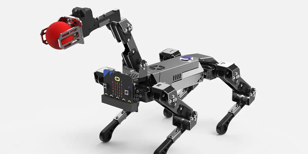
La differenza fondamentale tra aservomotoree un motore standard è il circuito di feedback. Un motore a induzione standard funziona ad anello aperto: si applica potenza e ruota senza segnalare la sua posizione o velocità effettiva.
Un servomotore fa il contrario. Confronta costantemente il valore comandato (posizione, velocità o coppia) con il valore effettivo misurato da un dispositivo di feedback. Se esiste una deviazione, il controller regola la potenza in uscita per correggerla. Questa correzione avviene centinaia o migliaia di volte al secondo.
Questa architettura a circuito chiuso è il motivo per cui i servosistemi possono mantenere la posizione sotto carichi variabili. Quando un braccio robotico preleva una parte più pesante, la richiesta di coppia aumenta. Il servocontrollore rileva il calo di velocità, aumenta la corrente e riporta il braccio nella posizione comandata prima che l'errore diventi visibile.
Senza questo circuito di feedback, anche il motore più potente non può garantire un posizionamento ripetibile. Per le applicazioni in cui la tolleranza viene misurata in micron o millisecondi, il controllo a circuito chiuso non è opzionale.
Come la modulazione di larghezza di impulso (PWM) controlla la posizione e la velocità
Il metodo più comune per comandare un servo è la modulazione di larghezza di impulso (PWM). Un segnale PWM è un'onda quadra in cui la durata dell'impulso "on", misurata in millisecondi, determina la risposta del motore.
Per i servi con controllo di posizione standard, un impulso da 1,0 ms comanda tipicamente la rotazione completa in una direzione, un impulso da 1,5 ms comanda la posizione centrale (neutra) e un impulso da 2,0 ms comanda la rotazione completa nella direzione opposta. Il controller legge l'ampiezza dell'impulso, la confronta con la posizione di feedback corrente e guida il motore in modo che corrisponda.
Nei servoazionamenti digitali più avanzati, il PWM funziona a frequenze più elevate. Una frequenza più elevata riduce il rumore udibile e migliora il tempo di risposta. L'esatto intervallo dell'ampiezza dell'impulso e il punto neutro variano in base al produttore e devono essere verificati rispetto alle specifiche dell'azionamento.
Il controllo della velocità tramite PWM segue una logica simile ma interpreta l'ampiezza dell'impulso come una velocità target anziché come una posizione fissa. Nei servi a rotazione continua, l'ampiezza dell'impulso sopra o sotto il punto neutro imposta la direzione e la velocità proporzionale.
Per gli acquirenti che selezionano asistema di servomotore, la conferma della compatibilità PWM tra il controller e l'unità è un passaggio fondamentale. Gamme di segnale non corrispondenti causano movimenti irregolari o la completa perdita di controllo.
Componenti chiave che consentono movimenti precisi
Un servosistema comprende quattro elementi essenziali: il motore, il dispositivo di feedback, l'azionamento e il controller.
Motore:Tipicamente un motore sincrono DC (BLDC) o AC senza spazzole progettato per accelerazioni e decelerazioni rapide.
Dispositivo di feedback:Un encoder o un risolutore che segnala la posizione, la velocità o la coppia effettiva. I risolutori sono più robusti in ambienti ad alte vibrazioni, mentre gli encoder offrono una risoluzione più elevata.
Azionamento (amplificatore):Converte i segnali di controllo a bassa potenza in corrente ad alta potenza per il motore. Inoltre interpreta il feedback e regola l'output.
Controllore:Il cervello del sistema. Genera il segnale di comando in base al programma applicativo e riceve feedback dal convertitore.
La qualità di ciascun componente influisce direttamente sulle prestazioni del sistema. Un encoder ad alta risoluzione migliora la precisione della posizione ma aumenta i costi del sistema. Un risolutore può essere più affidabile in ambienti sporchi ma offre una risoluzione inferiore.
Gli acquirenti devono valutare il tipo di feedback in base all'ambiente operativo, alla precisione richiesta e al programma di manutenzione. In molte applicazioni industriali, il dispositivo di feedback è il primo componente a guastarsi se esposto a calore eccessivo o contaminazione.
Metodi di controllo: modalità di posizione, velocità e coppia
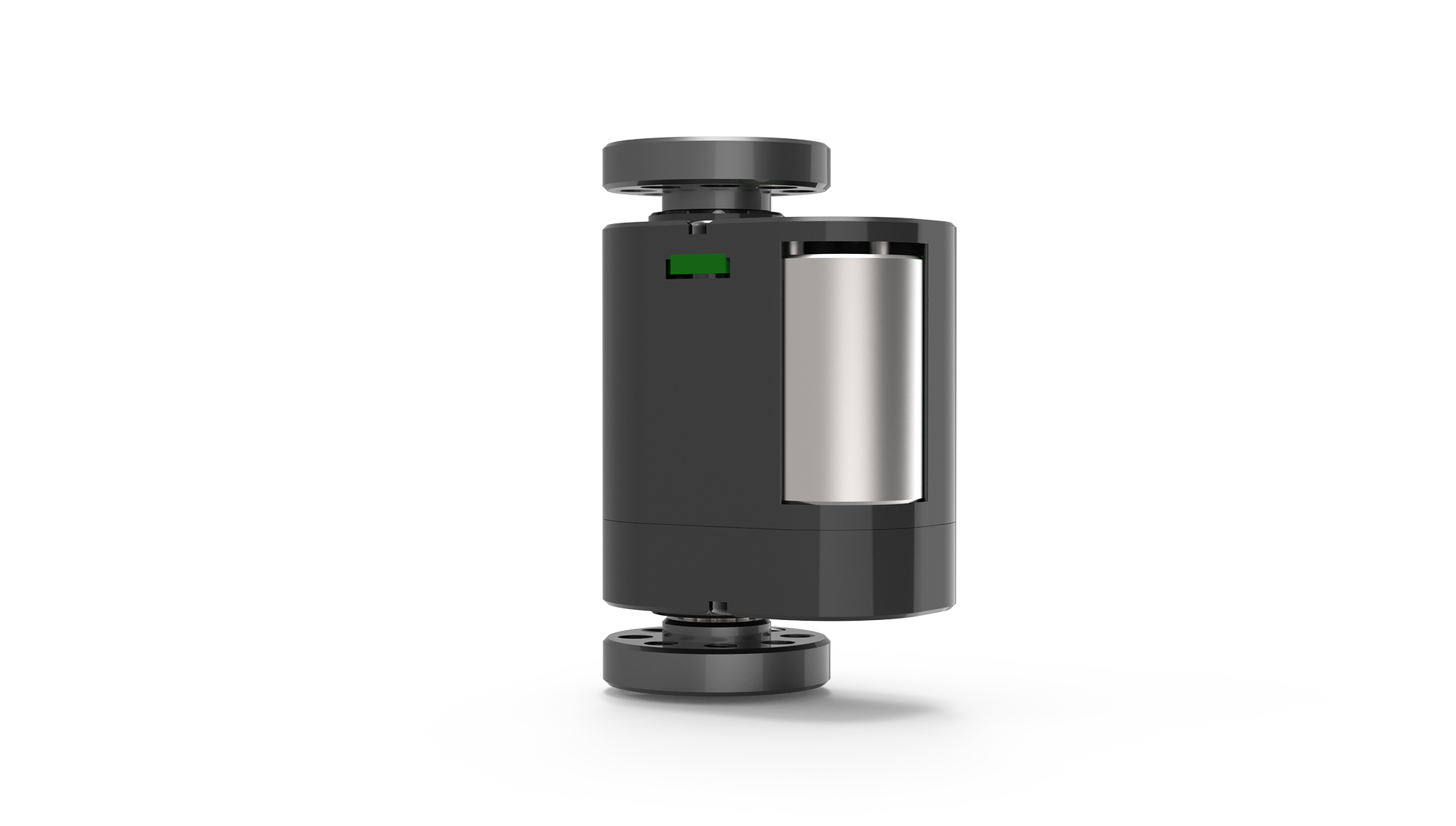
Modernoservoazionamentisupportare più modalità di controllo. La selezione della modalità corretta dipende dai requisiti dell'applicazione.
Modalità posizione:Il più comune. Il controller invia una posizione target e il servo si sposta in quella posizione con l'accelerazione e la decelerazione specificate. Utilizzato nel pick-and-place, nel posizionamento CNC e nell'indicizzazione.
Modalità velocità:Il controller invia una velocità target. Il servo mantiene quella velocità indipendentemente dalle variazioni di carico entro il limite di coppia. Utilizzato in trasportatori, mandrini e avvolgitrici.
Modalità coppia:Il controller invia un valore corrente target. Il servo applica una coppia costante indipendentemente dalla velocità. Utilizzato in applicazioni di controllo della tensione, pressatura e bloccaggio.
Molte unità avanzate consentono il passaggio da una modalità all'altra durante il funzionamento. Ad esempio, una macchina può utilizzare la modalità coppia durante una fase di pressatura, quindi passare alla modalità posizione per la corsa di ritorno.
La scelta della modalità sbagliata aumenta il tempo di ciclo e riduce la coerenza del processo. Un acquirente che specifica un servo per aapplicazione di controllo del movimentodovrebbe definire il requisito di controllo primario prima di selezionare l'azionamento.
Errori comuni nella selezione del servocontrollo
Numerosi errori ricorrenti aumentano i costi del progetto e ritardano la messa in servizio.
Innanzitutto, sottovalutare la coppia richiesta. Gli acquirenti spesso calcolano la coppia media ma ignorano la coppia di picco durante l'accelerazione. Un servomotore che soddisfa la coppia media ma non è in grado di gestire la domanda di picco va in stallo o attiva un guasto da sovracorrente.
In secondo luogo, ignorando il rapporto di inerzia. Il rapporto di inerzia carico-motore dovrebbe in genere rimanere inferiore a 10:1. Rapporti più elevati rendono difficile la regolazione, causano superamenti e riducono la stabilità del posizionamento.
In terzo luogo, presupponendo che tutti i segnali PWM siano compatibili. I servoazionamenti di produttori diversi possono utilizzare ampiezze di impulso, livelli logici o polarità diversi. Confermare sempre le specifiche del segnale di controllo confornitore di servomotori .
In quarto luogo, trascurare la qualità e la lunghezza del cavo. I cavi lunghi o non schermati introducono rumore nel segnale di feedback. Il rumore provoca jitter, deriva o la completa perdita di posizione.
Quinto: saltare la messa a punto del sistema. Anche un servosistema correttamente dimensionato funziona male senza un'adeguata regolazione del guadagno. L'ottimizzazione regola l'aggressività con cui il controller risponde agli errori. I sistemi sovrasintonizzati oscillano. I sistemi non sintonizzati sono lenti e imprecisi.
Domande che gli acquirenti fanno spesso sul servocontrollo
D: Qual è la differenza tra un servomotore e un motore passo-passo?
Un servomotore utilizza un feedback ad anello chiuso e può mantenere la posizione sotto carichi variabili. Un motore passo-passo si muove a passi discreti e spesso funziona ad anello aperto. I servi sono migliori per applicazioni ad alta velocità, coppia elevata o carico variabile. Gli stepper sono più semplici ed economici per attività a bassa velocità e a carico costante.
D: Come faccio a scegliere tra un servoazionamento analogico e uno digitale?
Gli azionamenti analogici accettano segnali ±10 V e sono più semplici ma meno precisi. Le unità digitali accettano comandi PWM, bus di campo o Ethernet e offrono ottimizzazione avanzata, diagnostica e controllo multimodale. Per le nuove installazioni industriali, gli azionamenti digitali rappresentano la scelta standard.
D: Posso utilizzare un servomotore senza azionamento?
No. Un servomotore richiede un azionamento per convertire i segnali di controllo a bassa potenza nella forma d'onda ad alta corrente necessaria per il funzionamento. Il collegamento di un servomotore direttamente a una fonte di alimentazione non produrrà un movimento controllato e potrebbe danneggiare il motore.
D: Cosa significa "accordatura del servo"?
La sintonizzazione è il processo di regolazione dei guadagni PID (proporzionale-integrale-derivativo) nell'azionamento o nel controller per adattarli al sistema meccanico. Una corretta messa a punto riduce al minimo il superamento, il tempo di assestamento e l'errore di stato stazionario. Un'accordatura errata provoca oscillazioni, rumore o risposta lenta.
D: In che modo la lunghezza del cavo influisce sulle prestazioni del servo?
I cavi di feedback lunghi aumentano la resistenza e la suscettibilità al rumore elettrico. Per i segnali dell'encoder, le lunghezze dei cavi superiori a 10–15 metri richiedono in genere un segnale differenziale o un ripetitore di segnale. I cavi di alimentazione devono essere schermati e separati dai cavi di controllo.
D: Qual è la durata tipica di una spazzola per servomotore?
I servomotori brushless non hanno spazzole. La loro durata dipende dalla qualità dei cuscinetti, dalla temperatura operativa e dal carico. Negli ambienti industriali tipici, un servomotore brushless funziona da 20.000 a 40.000 ore prima che sia necessaria la sostituzione dei cuscinetti.
D: Un servomotore può mantenere la posizione senza alimentazione?
No. La maggior parte dei servomotori non dispone di freno meccanico. Quando viene rimossa l'alimentazione, il motore gira liberamente a meno che non sia integrato un freno di stazionamento separato. Per gli assi verticali o caricati per gravità è necessario un freno per motivi di sicurezza.
D: Qual è la differenza tra encoder incrementali e assoluti?
Un encoder incrementale segnala i cambiamenti di posizione relativi da un punto di riferimento. Un encoder assoluto segnala la posizione esatta in ogni momento, anche dopo un'interruzione di corrente. Gli encoder assoluti eliminano la necessità di una routine di homing ma costano di più e in alcuni progetti richiedono una batteria di backup.
Scegliere il giusto approccio di controllo per la tua applicazione
La selezione di un metodo di servocontrollo inizia con la definizione del profilo di movimento: l'attività è critica per la posizione, la velocità o la coppia? La risposta determina se è necessario un sistema in modalità posizione, velocità o coppia.
Successivamente, valutare l'ambiente operativo. La temperatura elevata, le vibrazioni o il rumore elettrico influenzano il tipo di feedback, le specifiche del cavo e la classificazione dell'involucro dell'unità. Un industrialeservomotoreinstallato vicino a una linea di saldatura richiede una protezione diversa rispetto a quella installata in una camera bianca.
Quindi, considera la compatibilità del controller. Non tutti i controllori supportano tutti i protocolli del bus di campo. Se il PLC esistente utilizza EtherCAT, il servoazionamento deve supportare EtherCAT. La mancata corrispondenza del protocollo è un ostacolo comune all’integrazione.
Infine, collabora con un fornitore che fornisca specifiche dettagliate, supporto applicativo e indicazioni per l'ottimizzazione. Un servosistema non è un componente plug-and-play. La differenza tra un sistema che funziona a malapena e uno che fornisce un rendimento costante spesso dipende dal dimensionamento corretto, dalla selezione del metodo di controllo e dal supporto per la messa in servizio.
Akpowerservo, aiutiamo gli acquirenti a valutare i loro requisiti di movimento, ad abbinare i metodi di controllo alle esigenze dell'applicazione ed a evitare errori di integrazione comuni. Se stai attualmente confrontando le opzioni dei servo o hai bisogno di assistenza per selezionare il giusto approccio di controllo, contatta il nostro team di ingegneri con i dettagli della tua applicazione.
Tempo di aggiornamento: 2026-07-08

Contatta lo specialista di prodotto Kpower per consigliare il motore o il riduttore adatto al tuo prodotto.


